Form I-X, P/N 150491 R7, Page 29
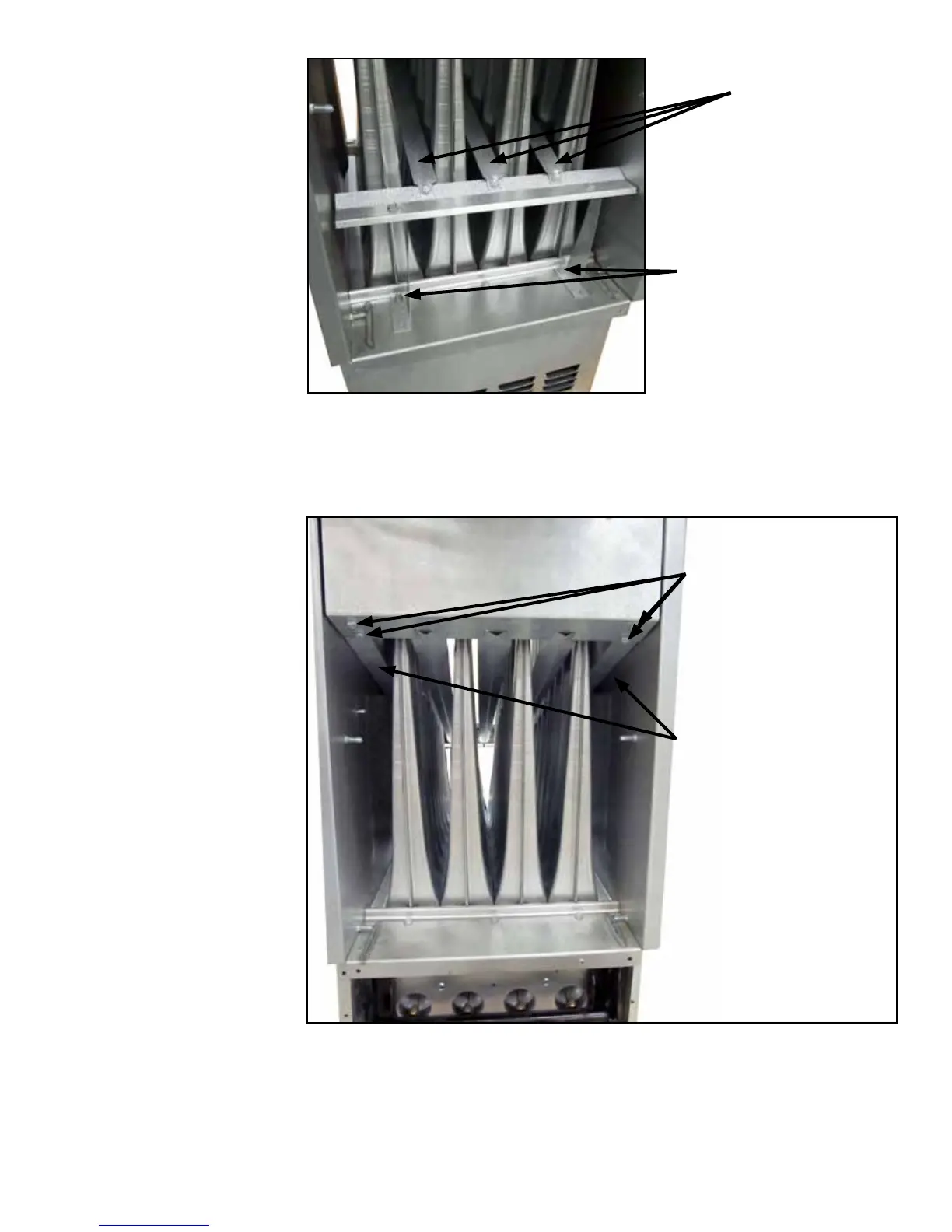
FIGURE 28 - Discharge
Air End of the Heat
Exchanger showing the
Bafe Assembly to be
Removed
Conversion is complete for Sizes 75-100; skip to Step 4.
3. Sizes 125-400 only - Remove the Side Finger Bafes – Refer to FIGURE 29
showing the entering air side of the heat exchanger (bafes shown in FIGURE 28
have already been removed). Identify the side nger bafes. Remove both side
bafes; each bafe is attached with two screws.
Remove the support
bracket screws and slide
the bafe assembly out
of the heat exchanger.
Replace the screws to
plug the holes.
Bafes (Remove
with the supports
as an assembly.)
Conversion is complete for Sizes 125-400; continue to Step 4.
4. Select a location adjacent to the rating plate for the conversion label. Being sure
the surface is clean and dry, adhere the conversion label that was completed in
Step 1.
Test for proper operation. Be sure to comply with the air throughputs in the table on
page 28.
FIGURE 29 - Entering
Air End of the Heat
Exchanger showing the
Side Finger Bafes to
be Removed
Remove the two
screws from each
of the side nger
bafes. Remove both
bafes.
Heat exchanger side
nger bafes being
removed (Sizes 125-
400 only).
NOTE: Do NOT
remove these side
nger bafes on
Sizes 75 and 100.