8
Operating and installation instructions RF-KIT Power Amplifier RF2K-S
5. Using the device locally
5.1 Turning device on/o
► Turn on the device using power switch On/O (1).
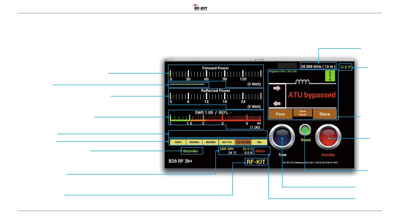
The Touchscreen (2) lights up and shows the user interface:
Indication area Forward Power (analog PEP and digital Minimal / Maximal)
Indication area Input Power
Indication area Reected Power (analog PEP and digital Minimal / Maximal)
Indication area SWR (analog PEP and digital Minimal / Maximal)
Indication area Error Messages
Indication area Choosen band
Switching area/Indication area Actually Choosen Antenna
Switching area
Interface
Switching between
„UDP“ / „CAT“
Switching area/
Indication area
Antenna Tuner
Indication area Operating Parameters
(selected interface, end transistor supply voltage, output stage temperature, output stage current consumption)
Indication area Personalization Text
An individualization text to be edited in the user menu (e.g. call sign) is displayed here
Switching area Menu
Touching this switching area activates the user menu
Indication area
Frequency TRX
Switching area Tune
Touching this switching area triggers a tuning process
Switching area
Reset PA
If the PA switches o due to an error, it is reactivated after actuating this switching
area; the error message (e.g. „zu hohes SWR“ vanishes)
Switching area
Standby
Switching between
„Standby“ (red)
„Operate“ (green)