20
Operating and installation instructions RF-KIT Power Amplifier RF2K-S
6. Antenna tuner
6.1. Operation
The LC network in a antenna tuner is to compensate reactive components
and to provide power adjustment, so the antenna radiates supplied TX
power Peff via the radiation resistance R.
This requires:
- compensation of reactance jX = j(ωL-1/ωC) of the antenna system
and
- transformation of the effective resistance for power adaptation of the
transmitter to the antenna system.
(Antenna system = antenna + impedance transforming feed line).
Available values of C: Minimal 0,0 pF; Max. 1275 pF
Available values of L: Minimal 0,0 μH; Max. 10,16 μH
The integrated antenna tuner can perform this „at the push of a button“ for
you automatically (tuner mode „AUTO“). In this mode, the antenna tuner
automatically determines the required configuration and does all settings.
Beside of that, you have the option of performing the tuning process
manually (tuner mode „MAN“) or refine a configuration that has already
been determined before.
Regardless how a setting has been determined, all of the values can be
stored for later retrieval, so a re-tuning process is superfluous.
A separate database will be created for each antenna connector, in which
all already determined settings for this antenna will be stored.
Depending on the currently selected antenna connector, only settings
stored for this antenna connector will be considered during operation. The
antenna tuner continually checks for the availability of a suitable, already
stored setting for the currently selected antenna connector while tuning
a frequency.
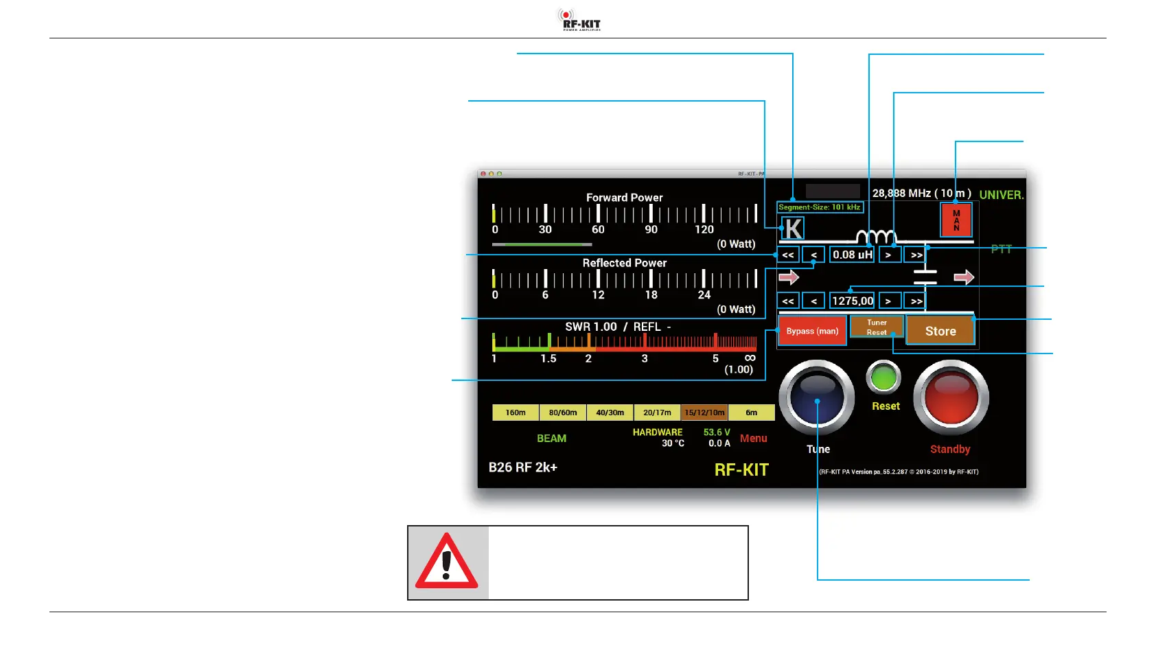
Indication area L
(in μH)
Switching area Tune
Pressing this switching area triggers a tuning process of the antenna
Indication area Segment-Size
Switching area K
Selection conguration
antenna tuner
Switching area/Display
Tuner-Mode
Selection
„Auto“ (green) /
„Man“ (red)
Indication area C
(indication in pF)
Switching area >>
Increase value
coarse
Switching area >
Increase value
ne
Switching area
<<
Decrease value
coarse
Switching area <
<
Decrease value
ne
Switching
area Bypass
Selection „Pass“ /
„Bypass“
Switching area
Store
Switching area
Tuner Reset
NOTE:
If the antenna tuner is activated, but no valid
tuning is stored yet for the used frequency, trans-
mitting is not possible!