EasyManua.ls Logo

Rheem 13PJL42A01 User Manual

Rheem 13PJL42A01
32 pages
To Next Page IconTo Next Page
Page #1 background imageLoading...
Page #1 background image
92-20522-57-03
SUPERSEDES 92-20522-57-02
INSTALLATION INSTRUCTIONS
WARNING
WARNING
!
These instructions are intended as an aid to qualified licensed
service personnel for proper installation, adjustment and
operation of this unit. Read these instructions thoroughly
before attempting installation or operation. Failure to follow
these instructions may result in improper installation, adjust-
ment, service or maintenance possibly resulting in fire, electri-
cal shock, property damage, personal injury or death.
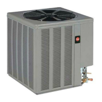
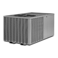
NOTE: Appearance of unit may vary.
13 & 14 SEER SERIES
CUBE HEAT PUMPS
1
1
2 - 5 TONS FEATURING
EARTH-FRIENDLY R-410A REFRIGERANT R-410
refrigerant
earth friendly refrigerant
Question and Answer IconNeed help?

Do you have a question about the Rheem 13PJL42A01 and is the answer not in the manual?

Rheem 13PJL42A01 Specifications

General IconGeneral
Model Number13PJL42A01
CategoryHeat Pump
Cooling Capacity42000 BTU
Heating Capacity42000 BTU
Voltage208/230V
Phase1
RefrigerantR-410A
Compressor TypeScroll

Summary

1.0 SAFETY INFORMATION

3.7 FACTORY-PREFERRED TIE-DOWN METHOD

4.0 REFRIGERANT CONNECTIONS

7.6 LEAK TESTING

8.0 DEMAND DEFROST CONTROL

8.4 TEST MODE

8.5 DEMAND DEFROST OPERATION

8.6 TROUBLE SHOOTING DEMAND DEFROST

9.0 EVACUATION PROCEDURE

10.0 START UP AND PERFORMANCE

11.0 CHECKING AIRFLOW

12.0 CHECKING REFRIGERANT CHARGE

12.2 CHARGING BY WEIGHT

12.3 FINAL LEAK TESTING

13.0 ELECTRICAL WIRING

13.2 GROUNDING

Requirement and method for permanently grounding the unit to prevent electrical shock.

13.3 CONTROL WIRING

15.0 SERVICE

16.0 TROUBLE SHOOTING

16.1 ELECTRICAL CHECKS FLOW CHART

A flowchart to diagnose electrical issues when the unit does not run.

16.2 COOLING MECHANICAL CHECKS FLOW CHART

Flowchart for diagnosing mechanical problems affecting cooling performance.

16.3 HEATING MECHANICAL CHECKS FLOW CHART

Flowchart for diagnosing mechanical problems affecting heating performance.

16.4 DEFROST MECHANICAL CHECKS FLOW CHART

Flowchart to troubleshoot issues related to the defrost system of the heat pump.

16.5 SUBCOOLING CALCULATION

Steps to calculate subcooling using pressure and temperature measurements for charge verification.

16.6 GENERAL TROUBLE SHOOTING CHART

A comprehensive chart listing symptoms, causes, and remedies for common heat pump issues.

16.7 SERVICE ANALYZER CHART

Troubleshooting guide for compressor overheating and related electrical issues.

Related product manuals