Do you have a question about the Rheem 13 Series and is the answer not in the manual?
Covers electrical shock, warranty, and operational safety risks.
Emphasizes permanent grounding and safe electrical connections.
Recommends secondary pan to prevent property damage from leaks.
Warns about servicing single-pole contactors as only one leg is broken.
Procedures for checking received unit for damage and correct specifications.
Discusses duct analysis, heat gain calculation, and installer considerations.
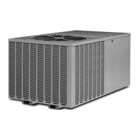
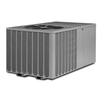
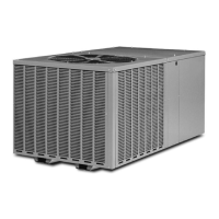
Details physical dimensions and clearance requirements for the unit.
Lists electrical and physical data for 13 SEER and 14 SEER models.
Discusses impact of corrosive elements and protective measures for unit longevity.
Recommends optimal placement for performance, life, and serviceability.
Addresses interference, water runoff, and freezing conditions.
Provides specific clearance allowances for units with limited space.
Advises locating unit away from living spaces to minimize noise transmission.
Guidelines for elevating units on roofs or slabs, ensuring stability.
Instructions for securing the unit against high wind loads.
Emphasizes keeping tube ends sealed to prevent system contamination.
Details requirements for existing tubing in replacement unit installations.
Specifies placement within the duct system and drainage.
Guidance on selecting correct line sizes and charge adjustments.
Defines the limit for interconnecting tubing length and impact of length.
Rules for managing vertical distance between indoor and outdoor units.
Covers material, sealing, flushing, insulation, and protection.
Procedures for brazing, sealing, and connecting refrigerant lines.
Method for pressurizing and checking lines for leaks using nitrogen.
Criteria for starting a defrost cycle based on temperature and run time.
Explains how defrost cycles are terminated by time or temperature.
Details the role of coil and ambient sensors in defrost operation.
How to initiate and use the test mode for defrost cycle verification.
Key operational points and compressor protection during defrost cycles.
Steps to diagnose issues with the demand defrost control system.
Explains the critical role of proper evacuation for system life and efficiency.
Guidance on checking factory charge and initial operational parameters.
Discusses the significant impact of ductwork on system airflow and performance.
Method for charging the system based on liquid pressure readings.
Procedure for charging the system using weight and line set calculations.
Steps for detecting leaks after evacuation and charging.
Requirements for connecting main power supply, including disconnects and conduit.
Details the necessity and method for permanently grounding the unit.
Explains low voltage control wiring, thermostat connections, and transformer requirements.
Purpose and installation of CCH to prevent refrigerant migration.
Function of LAC to maintain performance in low ambient temperatures.
Role of HPC in protecting the compressor from overpressure conditions.
Caution regarding servicing single-pole contactors that only break one power leg.
A diagnostic guide for electrical issues affecting unit operation.
A diagnostic flow chart for cooling-related mechanical problems.
A diagnostic flow chart for heating-related mechanical problems.
A diagnostic flow chart for issues related to the defrost system.
Steps to measure and calculate subcooling for system charging.
Identifies causes and remedies for the unit failing to start.
Diagnoses issues where the outdoor fan operates but the compressor does not.
Addresses causes and solutions for inadequate cooling performance.
Explains why the compressor cycles on and off rapidly.
Troubleshooting for abnormal head and suction pressures in cooling mode.
Diagnoses problems leading to an iced indoor coil.
Addresses causes and remedies for high system vapor pressure.
Guides on diagnosing unstable head and vapor pressures.
Identifies causes for noise at the expansion device or liquid line.
Analyzes causes and remedies for compressor overheating symptoms.
Diagnoses problems related to low voltage affecting unit operation.
Addresses causes and solutions for high voltage impacting the unit.
Analyzes reasons for high head pressure and potential remedies.
Investigates causes for the compressor short cycling.
Diagnoses issues related to faulty compressor valves.
Troubleshooting electrical symptoms like no run or partial voltage.
Identifies causes of contamination like moisture or improper welding.
Diagnoses and resolves issues related to compressor lubrication.
Addresses causes and remedies for liquid refrigerant in the compressor shell.
Diagnoses problems causing liquid refrigerant slugging.
Identifies causes for flooding and poor system control.
Diagnoses issues causing high superheat and low suction pressure.
Addresses symptoms of too much refrigerant with low superheat.
Identifies causes of refrigerant flooding back to the compressor on startup.
Diagnoses issues leading to low superheat and low suction pressure.
Addresses causes of fluctuating superheat and suction pressure.
Diagnoses why the expansion valve fails to regulate properly.
Lists and explains the function of various components in the wiring diagram.
Details wire colors and provides general wiring information and warnings.
| Refrigerant | R-410A |
|---|---|
| Voltage | 208/230V |
| Compressor Type | Scroll |
| Cooling Capacity | 18, 000-60, 000 BTU/h |
| Heating Capacity | 18, 000-60, 000 BTU/h |
| Stages | Single |