EasyManua.ls Logo

Rheem 13PJL48A01 User Manual

Rheem 13PJL48A01
32 pages
To Next Page IconTo Next Page
Page #1 background imageLoading...
Page #1 background image
92-20522-57-03
SUPERSEDES 92-20522-57-02
INSTALLATION INSTRUCTIONS
WARNING
WARNING
!
These instructions are intended as an aid to qualified licensed
service personnel for proper installation, adjustment and
operation of this unit. Read these instructions thoroughly
before attempting installation or operation. Failure to follow
these instructions may result in improper installation, adjust-
ment, service or maintenance possibly resulting in fire, electri-
cal shock, property damage, personal injury or death.
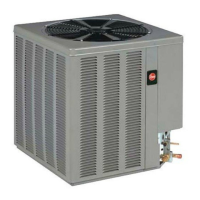
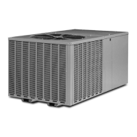
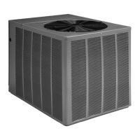
NOTE: Appearance of unit may vary.
13 & 14 SEER SERIES
CUBE HEAT PUMPS
1
1
2 - 5 TONS FEATURING
EARTH-FRIENDLY R-410A REFRIGERANT R-410
refrigerant
earth friendly refrigerant
Question and Answer IconNeed help?

Do you have a question about the Rheem 13PJL48A01 and is the answer not in the manual?

Rheem 13PJL48A01 Specifications

General IconGeneral
Model Number13PJL48A01
CategoryHeat Pump
Cooling Capacity (BTU/h)48000
Heating Capacity (BTU/h)48000
SEER Rating13
HSPF Rating7.7
Voltage (V)208/230
Phase1
Refrigerant TypeR-410A
Compressor TypeScroll

Summary

SAFETY INFORMATION

LOCATING UNIT

REFRIGERANT CONNECTIONS

INTERCONNECTING TUBING

VAPOR AND LIQUID LINES

Instructions for keeping lines sealed, connecting to the indoor coil first, and referencing line size information.

LEAK TESTING

Procedures for leak testing the line set and coil using dry nitrogen and detergent.

DEMAND DEFROST CONTROL

EVACUATION PROCEDURE

START UP AND PERFORMANCE

CHECKING REFRIGERANT CHARGE

FINAL LEAK TESTING

Using a halogen leak detector to find leaks after evacuation and charging.

ELECTRICAL WIRING

POWER WIRING

Instructions for installing power wiring, including disconnects, conduit, and connection points.

GROUNDING

Emphasizes the requirement for permanent grounding to prevent electrical shock.

CONTROL WIRING

Details on low voltage control wiring, thermostat requirements, and transformer needs.

SERVICE

TROUBLE SHOOTING

ELECTRICAL CHECKS FLOW CHART

A flowchart to diagnose electrical issues when the unit is not running.

COOLING MECHANICAL CHECKS FLOW CHART

A flowchart to diagnose mechanical problems during cooling operation.

HEATING MECHANICAL CHECKS FLOW CHART

A flowchart to diagnose mechanical problems during heating operation.

DEFROST MECHANICAL CHECKS FLOW CHART

A flowchart to diagnose issues related to the defrost system.

GENERAL TROUBLE SHOOTING CHART

A table listing common symptoms, possible causes, and remedies for system faults.

SERVICE ANALYZER CHART

A diagnostic chart for compressor overheating and related electrical issues.

WIRING DIAGRAM

Related product manuals