49
This document is stored and maintained electronically by Service. All printed copies are deemed uncontrolled.
TM077: 325 & 410 Series II Heat Pump Service Instructions
Rev 00: Issued April 2014
Component Tests 2 – 5
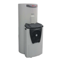
Remove the top electrical cover from the
storage tank and using a multimeter set on
the AC voltage scale, measure between
terminals 1 and 3 on the thermostat.
Normal voltage is 240V AC.
Using a multimeter set on the resistance
(ohms) scale, measure between the
terminals of the mechanical thermostat.
The following results should be obtained
when the ECO is closed:
1 & 2: 0 – 1Ω
3 & 4: 0 – 1Ω
Using a multimeter set on the resistance
(ohms) scale, measure between terminals
1 and 2 on the thermostat.
Normal resistance when the thermostat is
closed is 0 – 1Ω.
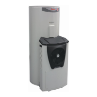
Remove the front cover from the heat
pump module and using a multimeter set
on the AC voltage scale, measure between
the active (red) and neutral (blue) terminals
of the mains plug at the controller.
Normal voltage is 240V AC.
 Loading...