EasyManua.ls Logo

Rheem 325 II Series User Manual

Rheem 325 II Series
76 pages
To Next Page IconTo Next Page
Page #1 background imageLoading...
Page #1 background image
First Issued April 2014
This document is stored and maintained electronically by Service. All printed copies are deemed uncontrolled.
Rheem Australia Pty Ltd ABN 21 098 823 511
Solahart
Everhot
RheemPlus
Rheem
325HAV
251325
554325
451325
251410
554410
551325
551410
SERVICE INSTRUCTIONS
325 & 410 Series II Heat Pump
TM077
Revision: 00
Issued: April 2014
Question and Answer IconNeed help?

Do you have a question about the Rheem 325 II Series and is the answer not in the manual?

Rheem 325 II Series Specifications

General IconGeneral
Series325 II Series
CategoryHeat Pump
Voltage208/230V
Phase1
RefrigerantR-410A

Summary

INTRODUCTION AND SAFETY

General Safety Precautions

Covers warnings, PPE, and safe operation practices.

HEAT PUMP WATER HEATER MODEL IDENTIFICATION

Model Identification by Brand

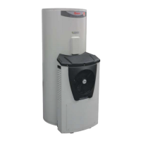
Details model number breakdown for Rheem, Everhot, Solahart, and AquaMax.

HEAT PUMP WATER HEATER MODELS

SPECIFICATIONS

Storage Tank

Details technical specifications for storage tanks across different models.

Heat Pump Module

PREVENTATIVE MAINTENANCE

Annual Service

Outlines routine checks for annual servicing of the unit.

Five Year Service

Details essential checks and replacements recommended every five years.

REFRIGERATION TERMS AND THEIR MEANING

COMPONENTS AND THEIR FUNCTION

Compressor

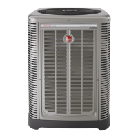
Describes the electromechanical device that increases refrigerant pressure.

Condenser

Explains the heat exchanger's role in transferring heat from refrigerant to water.

Evaporator

Filter Drier

Heating Element

CONTROLLER

Power and Tank Sensor Connections

Illustrates how power and tank sensors connect to the controller.

Sensors

Identifies the four independent temperature sensors used in the system.

Reset Button

OPERATION

Heat Pump Operation Overview

Explains how the controller manages heat pump and element operation.

SYSTEM START-UP

STANDBY MODE

HEAT PUMP MODE

ELEMENT MODE

FAULT 9 - HEATING DISABLED

FREEZE PROTECTION

LED STATUS CODES

Operation Status Codes

Explains green LED for mode and red LED for faults.

LED STATUS CODE TABLES

OPERATIONAL SEQUENCES

System Start-Up and Standby Mode Flowchart

Illustrates start-up and standby operational logic.

Faults

Fault Diagnosis Flowcharts

Introduces the charts for diagnosing various faults.

WIRING DIAGRAM

TANK ASSEMBLY WIRING

Shows the wiring connections for the tank components.

HEATER MODULE ASSEMBLY WIRING

Illustrates wiring connections for the heat pump module.

REFRIGERATION SYSTEM DIAGRAM

COMMON COMPLAINTS

Water Quality Issues

Discusses discoloured and milky water causes and checks.

Usage and Plumbing Related Issues

SERVICE TECHNICIAN'S HEAT PUMP KIT

Service Kit Components

Details the kit and its components like service power cable and plugs.

Proxy Tank Sensor and Element Plug

FAULT FINDING

Fault Finding Flow Chart Table

Lists faults, chart numbers, and corresponding pages for diagnosis.

General Fault Diagnosis

Fault Finding Charts 1-3

Fault Finding Chart 4

Fault Finding Chart 5

Fault Finding Chart 6

Fault Finding Chart 7

Fault Finding Chart 8

Fault Finding Chart 9

Fault Finding Chart 10

Fault Finding Chart 11

Fault Finding Chart 11.1

Fault Finding Charts 11.3-11.5

Fault Finding Charts 11.6-11.7

Fault Finding Charts 11.8-11.9

Fault Finding Chart 11.10

Fault Finding Chart 11.11

COMPONENT TESTING

Sensor Testing

Details how to test the four temperature sensors.

Sensor Temperature/Resistance Table

Provides resistance values for sensors at different temperatures.

COMPONENT TESTS 2-5

Thermostat & Mains Plug Tests

Tests thermostat voltage/resistance and mains plug voltage.

COMPONENT TESTS 6-7

Element & Suction Pressure Tests

Tests element resistance and suction pressure.

COMPONENT TESTS 8-9

Discharge Pressure & TX Valve Tests

Tests discharge pressure and TX valve operation.

COMPONENT TESTS 10-13

Fan & Circulator Tests

Tests fan/circulator voltage, resistance, and capacitor.

COMPONENT TESTS 14-17

Circulator, HP Switch, Compressor Voltage Tests

Tests circulator resistance, HP switch, compressor voltage.

COMPONENT TESTS 18-19

Compressor Winding & Capacitor Tests

Tests compressor winding resistance and capacitor.

Refrigerant Charge Indicators

Discusses indications of correct, low, or overcharged refrigerant.

ELECTRICAL INSULATION TESTING

Insulation & Earth Continuity Tests

Details testing insulation resistance and earth continuity for safety.

COMPONENT REPLACEMENT PROCEDURES

Storage Tank Components Replacement

Procedures for replacing tank parts like T&PR valve, anode.

Anode, Thermostat, Element Replacement

Procedures for replacing anode, thermostat, and heating element.

Tank Sensor Replacement

Procedures for replacing the tank sensor.

Water Fittings Replacement

Procedures for replacing ball valve, check valve, connectors, and tempering valve.

Tempering Valve Adjustment

Steps to adjust the tempering valve for correct temperature.

HEAT PUMP MODULE PROCEDURES

Heat Pump Module Removal

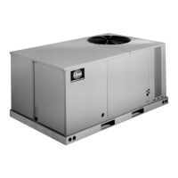
Step-by-step guide to safely remove the heat pump module.

Outer Jacket Removal

Procedure for removing and refitting the heat pump module outer jacket.

Controller Replacement

Procedure for removing and replacing the electronic controller.

Circulator & Sensor Replacement

Procedures for replacing circulator and sensors.

Other Module Components Replacement

Procedures for replacing LED panel, fan, and heat exchanger outlet sensor.

REFRIGERATION SYSTEM WORK

Safety Warnings and Requirements

Safety warnings and personnel qualifications for refrigeration work.

FILTER DRIER REPLACEMENT

Filter Drier Replacement Procedure

Steps for replacing the filter drier, including refrigerant handling.

COMPRESSOR REPLACEMENT

Compressor and High Pressure Switch Replacement

Procedures for replacing compressor and HP switch.

Discharge Check Valve Replacement

HEAT EXCHANGER REPLACEMENT

Heat Exchanger Replacement Steps

Steps for removing and replacing the heat exchanger.

SIGHT GLASS AND TX VALVE

Sight Glass and Filter Drier Replacement

Procedure for replacing the sight glass and filter drier.

TX Valve Adjustment

Steps to adjust the TX valve for optimal superheat.

TX Valve Replacement

EVAPORATOR COIL REPLACEMENT

Evaporator Coil Replacement Steps

Steps for removing and replacing the evaporator coil.

DOCUMENT REVISION HISTORY

Related product manuals