70
This document is stored and maintained electronically by Service. All printed copies are deemed uncontrolled.
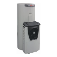
TM077: 325 & 410 Series II Heat Pump Service Instructions
Rev 00: Issued April 2014
Heat Exchanger (Condenser) (2 hours*)
WARNING: Heat must NOT be applied to plastic components. When brazing
pipework as indicated in this procedure, a heat shield must be used to
prevent the possibility of damage.
1. Remove the heat pump module. Refer to the „Heat Pump Module Removal‟ procedure
on page 62.
2. Remove the heat pump module outer jacket. Follow steps 6 – 14 of the „Outer Jacket‟
procedure on page 62.
3. Remove the controller. Follow steps 5 – 8 of the „Controller‟ procedure on page 63.
4. Remove the circulator. Follow steps 4 – 6 of the „Circulator‟ procedure on page 64.
NOTE: Only the circulator‟s heat exchanger connection need be undone – the flexible
hose on the other connection may be removed with the circulator.
5. Remove the heat exchanger water outlet sensor. Follow steps 3 – 5 of the „Heat
Exchanger Water Outlet Sensor‟ procedure on page 65.
6. Remove the flexible hose from the top water fitting on the heat exchanger.
7. Remove the pipe insulation from the discharge line.
8. Remove the compressor sensor from the discharge line.
9. Recover the refrigerant from the sealed refrigeration system.
10. Disconnect the filter drier from the sight glass.
11. Disconnect the discharge line from the compressor.
12. Remove the 2 screws securing the evaporator coil to the chassis side member, on the
heat exchanger end only.
13. Gently lift the evaporator coil to create enough clearance to lift and slide the heat
exchanger assembly out of the heat pump module, whilst carefully releasing any
cabling from fixings as required. The heat exchanger assembly will need to be lifted
high enough to allow the heat exchanger bottom bracket tabs to be clear of the chassis
base.
14. Slide the brackets off the top and bottom of the heat exchanger.
15. Cut the cable tie retaining the styrene insulation to the heat exchanger, and remove the
insulation.
16. Remove the union assembly from the bottom water fitting on the heat exchanger.
17. Disconnect the liquid line tail (and filter drier) and the discharge line assembly from the
heat exchanger. Note the orientation of the pipework to ensure they are correctly
positioned in the replacement heat exchanger.
18. Disconnect the filter drier from the liquid line tail and replace with a new filter drier.
The following steps MUST be carried out on the removed filter drier:
Empty any retained oil out of the filter drier into a safe oil collection container,
whilst holding the filter drier at a safe distance and taking care to ensure the
pipes are never pointed towards the face.
Remove the pipe caps from the new filter drier and install the caps onto the
removed filter drier and sight glass assembly. The caps may be split so be sure
to securely tape the caps in place on the removed filter drier.
 Loading...
