13
HORIZONTAL UNITS
1. Position the unit to minimize long runs of duct or runs of
duct with many turns and elbows.
2. Unit can be mounted left or right side airflow configura-
tion.
3. Position the unit on adequate supports or by using
support brackets (see Figure 8) and connect supply
plenum.
4. If summer air conditioning is desired, position the in-
door coil on the supply air side of the unit. Insure that
no air can bypass this coil.
5. Secure the four angle brackets to the return air open-
ing. See Figure 9. Connect the return air ducting to the
return air opening at the top of the unit. Make the con-
nection air tight to prevent entraining combustion gases
from an adjacent fuel-burning appliance.
NOTE: Do not block furnace access with support rods.
Maintain clearances recommended in Figure 8. Allow
enough space for proper service maintenance or re-
placement of the heat exchanger and blower assem-
bly.
DUCTING
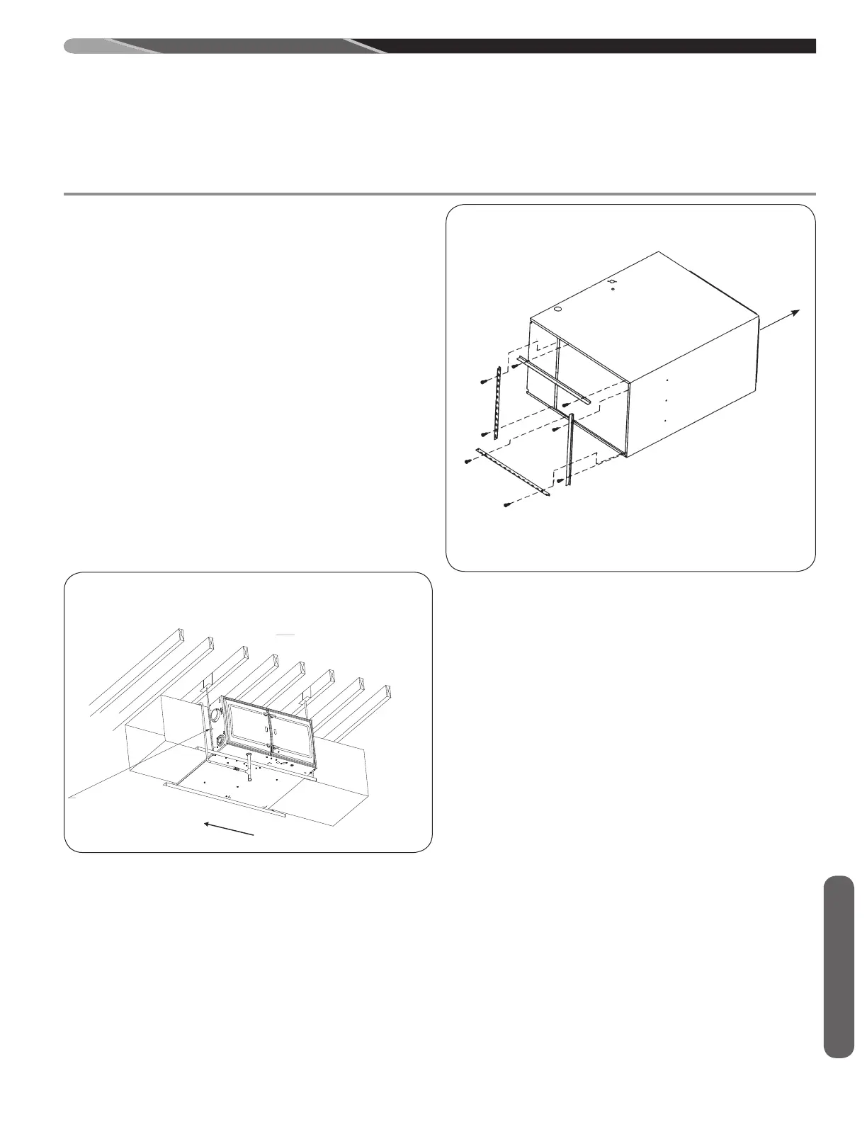
FOUR ANGLE BRACKETS, SHIPPED WITH 80% SINGLE STAGE
CONSTANT TORQUE UNITS, CAN BE INSTALLED HORIZONTALLY.
THESE BRACKETS MAY BE USED TO SECURE THE RETURN AIR
DUCT TO A HORIZONTAL UNIT.
RETURN
AIRFLOW
REAR VIEW
FIGURE 9
HORIZONTAL RETURN AIR DUCT
(LEFT-HAND AIRFLOW POSITION SHOWN)
ST-A1220-03-X0
NOTE:
HORIZONTAL LEFT ORIENTATION DEPICTED IN ILLUSTRATION.
HORIZONTAL RIGHT ORIENTATION IS SIMILAR IN INSTALLATION.
AIR FLOW
NOTE:
DO NOT BLOCK FURNACE ACCESS WITH
SUPPORT RODS, ALLOW SPACE FOR
PROPER SERVICE MAINTIENCE OR
REPLACEMENT OF THE HEAT EXCHANGER
AND BLOWER ASSEMBLY .
FIGURE 8
HORIZONTAL FURNACE INSTALLED W/SUPPORT BRACKETS
ST-A1220-03
Ducting
 Loading...