43
ADJUSTING OR CHECKING FURNACE INPUT
The maximum gas supply pressure to the furnace should be
10.5” w.c. for natural gas and 13.0” w.c. for L.P. The minimum
gas supply pressure for purposes of input adjustment to the fur-
nace should be 5” w.c. for natural gas and 11.0” w.c. for L.P.
A calibrated manometer is required for accurate gas pressure
readings.
The manifold pressure should be set at 3.5” w.c. for natural
gas and 10.0” w.c. for L.P. Only small variations in the gas flow
should be made by means of the pressure regulator adjustment.
In no case should the final manifold pressure vary more than
plus or minus 0.3” w.c. from the above- specified pressures. To
adjust the pressure regulator, remove the regulator cap and turn
the adjustment screw clockwise to increase pressure or coun-
terclockwise to decrease pressure. Then replace the regulator
cap securely. Any necessary major changes in the gas flow rate
should be made by changing the size of the burner orifices.
To change orifice spuds, shut off the manual gas valve and re-
move the gas manifold. On LP gas furnaces, the LP gas supply
pressure must be set between 11” and 13” w.c. by means of the
tank or branch supply regulators. The furnace manifold pressure
should be set at 10” w.c. at the gas control valve. For eleva-
tions up to 2,000 feet, rating plate input ratings apply. For high
altitudes (elevations over 2,000 ft.), see conversion kit index for
derating and orifice spud sizes.
Checking furnace input is important to prevent over firing be-
yond its design-rated input. NEVER SET INPUT ABOVE THAT
SHOWN ON THE RATING PLATE. Use the following table or
formula to determine input rate. Start the furnace and measure
the time required to burn one cubic foot of gas. Prior to checking
the furnace input, make certain that all other gas appliances are
shut off, with the exception of pilot burners. Time the meter with
only the furnace in operation. See Table 11.
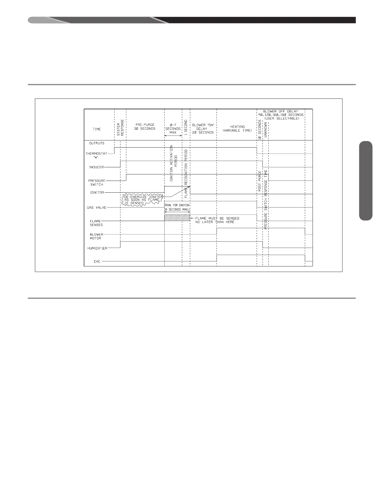
TABLE 10
TIMING DIAGRAM
ST-A1194-27-X0
OFF
OFF
OFF
OFF
OFF
OFF
OFF
OFF
OFF
OFF
OFF
OFF
OFF
OPEN
OFF
OFF
CLOSED
OPEN
ON
ON
ON
ON
ON
ON
OFF
ON
TIMING DIAGRAM, FIELD SELECTIONS &
ADJUSTMENTS
Field Selections
 Loading...