20
Combustion Air
COMBUSTION AND VENTILATION AIR (cont.)
VERTICAL VENT SYSTEMS:
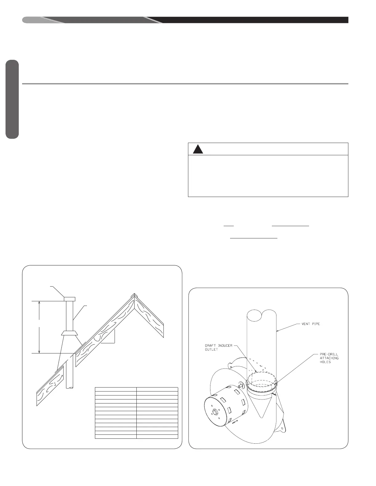
1. A gas vent shall terminate above the roof surface with a listed
cap or listed roof assembly. Gas vents 12 inches in size or
smaller with listed caps shall be permitted to be terminated in
accordance with Figure 15, provided they are at least 8 feet
from a vertical wall or similar obstruction. All other gas vents
shall terminate not less than 2 feet above the highest point
where they pass through the roof and at least 2 feet higher
than any portion of a building within 10 feet.
2. A type B-1 gas vent shall terminate at least 5 feet in vertical
height above the highest connected equipment draft hood or
flue collar.
3. Must rise
1
/4” per foot away from the furnace on horizontal
runs and be supported with straps or hangers so it has no
sags or dips. Supports at 4 foot intervals and at all elbows are
recommended.
4. The vent connector must be mechanically fastened to the
outlet collar of the furnace with at least (2) sheet metal screws
except vent connectors that are B-1 material. These shall be
assembled in accordance with the manufacturer’s instruc-
tions. See Figures 16 and 17.
5. Any angle greater than 45 degrees from the vertical is con-
sidered horizontal. The total horizontal distance of a vent plus
the horizontal vent connector serving draft-hood equipped
appliances shall not be greater than 75 percent of the vertical
height of the vent.
Single appliance venting of a fan assisted furnace into a tile-
lined masonry chimney is prohibited. The chimney must be lined
with either Type B vent or with a listed, single wall, metal lining
system. Reference National Fuel Gas Code, ANSI Z223.1. See
Figure 18 for typical B-1 vent chase.
NOTE: A chimney adapter is available as an accessory (see
accessory section of this manual). Follow manufacturer’s in-
structions.
SPECIAL VENT SYSTEMS (SVS)
IMPORTANT: It is THE FURNACE MANUFACTURER’s posi-
tion now that new installations of any HTPV pipe used in a cate-
gory III vent application, including Selkirk’s Selvent™ II HTPV
product, should cease immediately.
!
WARNING
DO NOT CONNECT THIS FURNACE TO A CHIMNEY USED
TO VENT A SOLID FUEL APPLIANCE (WOOD OR COAL).
VENTING WITH A SOLID FUEL APPLIANCE CAN LEAD
TO IMPROPER FUNCTIONING OF THE UNIT, AND DUE
TO SOOTING, THE POSSIBILITY OF FIRE RESULTING IN
PROPERTY DAMAGE, PERSONAL INJURY OR DEATH.
A0991-01
FIGURE 16
ATTACHING TO DRAFT INDUCER COLLAR
LISTED CAP
LISTED GAS VENT
ROOF PITCH = X/12
12
X
“H” - MINIMUM ALLOWABLE HEIGHT
FROM ROOF TO DISCHARGE OPENING
FIGURE 15
TYPICAL VENTING WITH “B-1” VENT
ROOF PITCH “H” (MIN.) FT.
FLAT TO 6/12 1.0
OVER 6/12 TO 7/12 1.25
OVER 7/12 TO 8/12 1.5
OVER 8/12 TO 9/12 2.0
OVER 9/12 TO 10/12 2.5
OVER 10/12 TO 11/12 3.25
OVER 11/12 TO 12/12 4.0
OVER 12/12 TO 14/12 5.0
OVER 14/12 TO 16/12 6.0
OVER 16/12 TO 18/12 7.0
OVER 18/12 TO 20/12 7.5
OVER 20/12 TO 21/12 8.0
ST-A1220-24
FIGURE 15
TYPICAL VENTING WITH “B-1” VENT
ST-A1220-24
 Loading...