28
Electrical Wiring
ELECTRICAL CONNECTIONS
Before proceeding with the electrical connections, be certain
that the voltage, frequency and phase corresponds to that spec-
ified on the furnace rating plate. For single furnace application,
maximum over-current protection is 15 amperes.
Use a separate fused branch electrical circuit containing a prop-
erly sized fuse or circuit breaker. Run this circuit directly from
the main switch box to an electrical disconnect that is readily
accessible and located near the furnace (as required by code).
Connect from the electrical disconnect to the junction box on the
left side of the furnace, inside the blower compartment. For the
proper connection, refer to the appropriate wiring diagram lo-
cated on the inside cover of the furnace control box and in these
instructions.
NOTE: The electrical junction box may be moved to the right
side if necessary. A knockout is provided. Seal the opposite hole
with plug provided.
NOTE: L1 (hot) and L2 (neutral) polarity must be observed
when making field connections to the furnace. The ignition con-
trol may not sense flame if L1 and L2 are reversed. Make all
electrical connections in accordance with the latest edition of the
National Electrical Code ANSI/NFPA70.
These may be obtained from:
National Fire Protection Association, Inc.
Batterymarch Park
Quincy, MA 02269
REVERSING THE ELECTRICAL
CONNECTION (JUNCTION BOX)
NOTE: Reversing the junction box is not possible in 14.0 inch
cabinets.
If the line voltage electrical needs to be moved to the opposite
side of the furnace, the following steps should be taken:
1. The furnace must NOT be electrically connected to line volt-
age prior to reversing the electrical connection.
2. Disconnect the wires from the door switch.
3. Remove the junction box from the furnace cabinet wall by
removing the two screws that hold it to the cabinet. Leave
the wires connected to the junction box.
4. Remove 7/8” plug from hole opposite j-box location. Drill 2
@ 3/16” Ø holes in the jacket. NOTE: Dimples/marks are
provided in the sheet metal for correct drilling location.
5. Move the junction box to the opposite side of the cabinet.
Install using the two screws removed in step 3 above. Note
that all screws penetrating the junction box must be blunt –
no sharp tipped screws can be used.
6. Replace the plug from the opposite of the furnace (the new
j-box location) to the old j-box location and install qty=2 1/4”
plugs from parts bag in empty screw holes in old location of
j-box into the mounting screw holes in the old junction box
location.
ELECTRICAL WIRING
ELECTRICAL WIRING
WARNING
THE CABINET MUST HAVE AN UNINTERRUPTED
GROUND ACCORDING TO THE LATEST EDITION
OF THE NATIONAL ELECTRICAL CODE, ANSI/
NFPA70 OR LOCAL CODES THAT APPLY. DO NOT
USE GAS PIPING AS AN ELECTRICAL GROUND. A
GROUND SCREW IS PROVIDED IN THE JUNCTION
BOX. FAILURE TO DO SO CAN CAUSE ELECTRI-
CAL SHOCK RESULTING IN PERSONAL INJURY
OR DEATH.
WARNING
THIS FURNACE IS EQUIPPED WITH A BLOWER
DOOR SAFETY SWITCH. DO NOT DISABLE THIS
SWITCH. FAILURE TO FOLLOW THIS WARNING
CAN RESULT IN ELECTRICAL SHOCK, PERSONAL
INJURY OR DEATH.
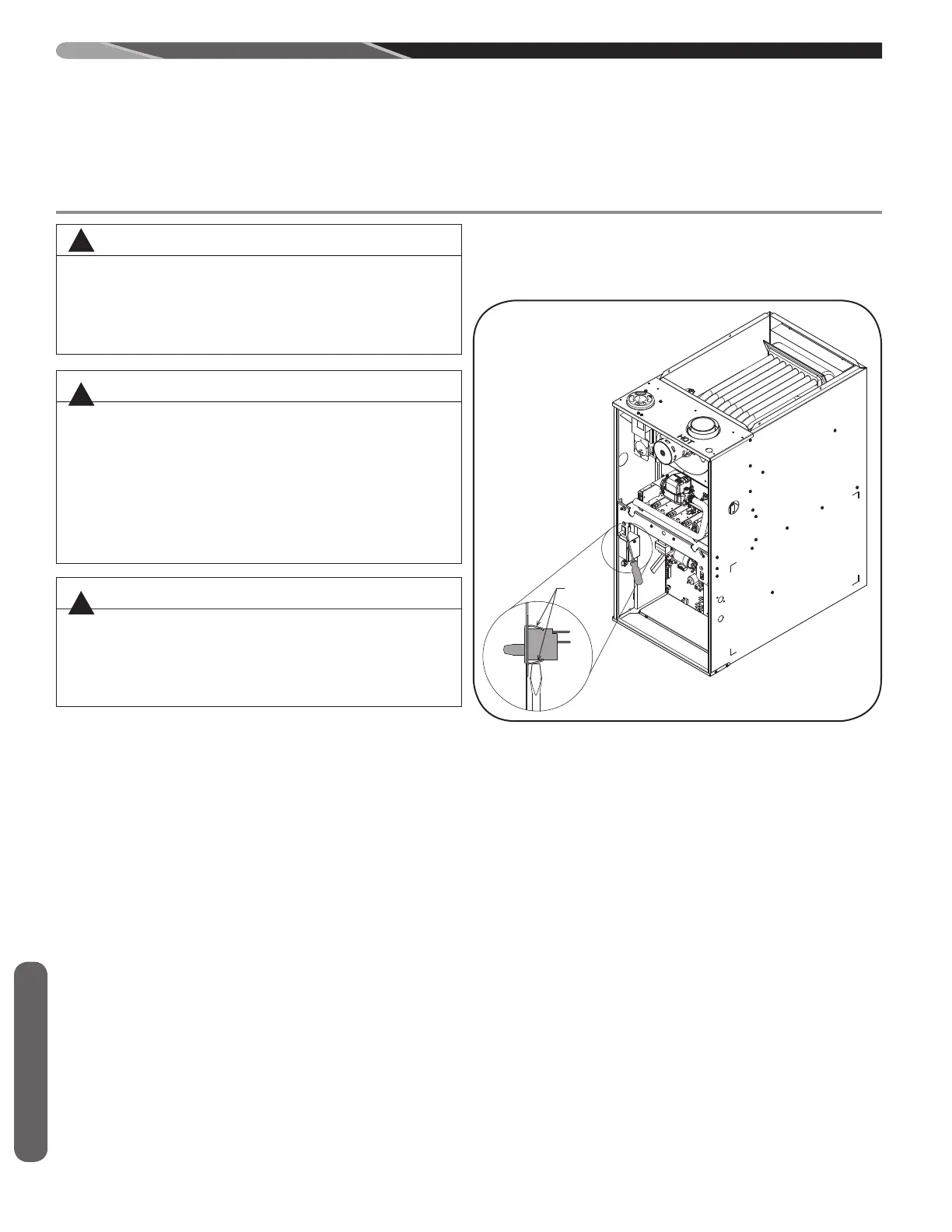
DOOR SWITCH
REMOVAL INSTRUCTIONS
LOCKING
TABS
FIGURE 22
ST-A1220-05
WARNING
TURN OFF ELECTRIC POWER AT FUSE BOX OR
SERVICE PANEL BEFORE MAKING ANY ELEC-
TRICAL CONNECTIONS. FAILURE TO DO SO CAN
CAUSE ELECTRICAL SHOCK RESULTING IN PER-
SONAL INJURY OR DEATH.
!
!
!
 Loading...