36
High Altitude
HIGH ALTITUDE
NATURAL GAS AT HIGH ALTITUDES (cont.)
TABLE 8
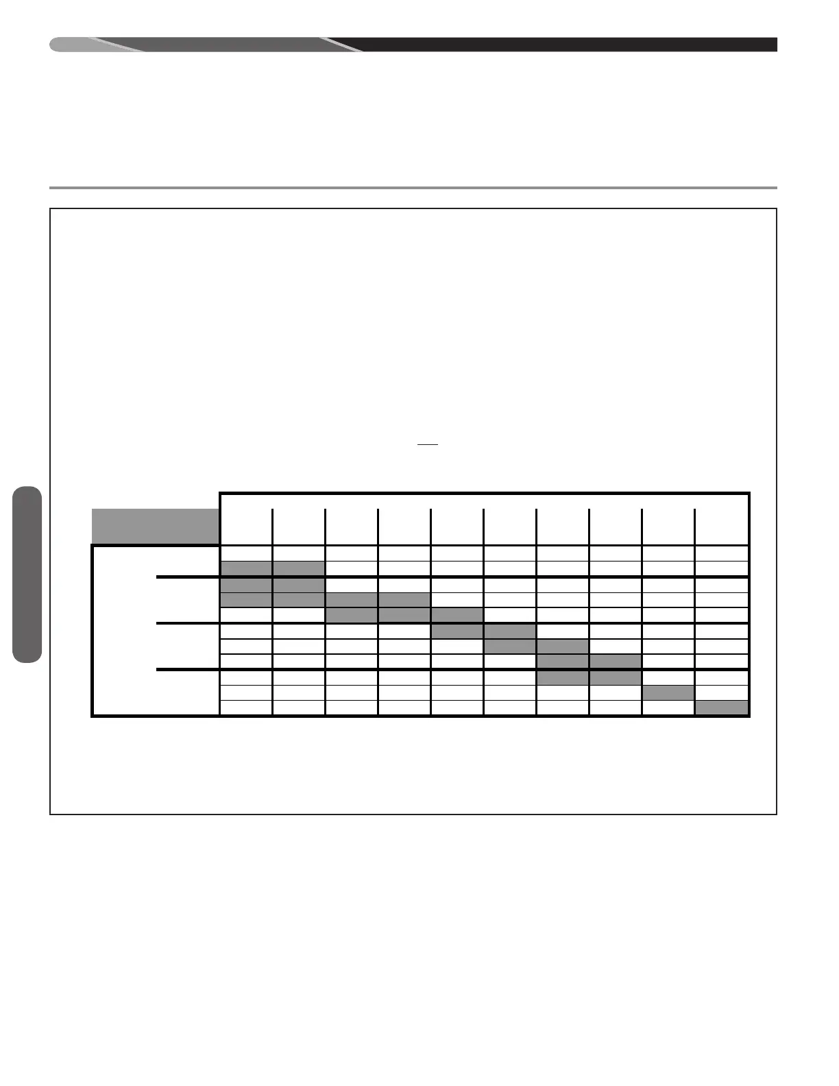
SUPPLEMENTAL ORIFICE SIZE CHART
Notes:
3. This chart is based on the National Fuel Gas Code (NFGC) Annex F based on natural gas with a secific gravity of 0.60
Sea Level
to 1,999'
2,000' to
2,999'
3,000' to
3,999'
4,000' to
4,999'
5,000' to
5,999'
6,000' to
6,999'
7,000' to
7,999'
8,000' to
8,999'
9,000' to
9,999' 10,000'
43 44 44 44 45 45 46 47 47 48
42 42 43 43 43 44 44 45 46 47
42
42 43 43 43 44 44 45 46 47
41
42 42 42 43 43 44 44 45 46
40
41
42
42 42 43 43 44 44 45
39
40 41 41 42 42 43 43 44 44
38
39 40 41 41 42 42 43 43 44
37
38 39 39 40 41 42 42 43 43
37
38 39 39 40 41 42 42 43 43
36
37 38 38 39 40 41 41 42 43
35
36 36 37 37 38 39 40 41 42
5. Furnace operation is optimized when operating at design rate. Installer is responsible to verify rate.
6. This table applies to 80+ models only with 25,000BTU/Burner. DO NOT USE THIS CHART FOR ANY 90+ FURNACE MODEL.
NATURAL GAS ORIFICE SELECTION BASED ON HEATING VALUE & ELEVATION*
*Table is derived from Appendix of the National Fuel Gas Code . To determine the correct orifice for your installation consult the National
Fuel Gas Code tables F.1 and F.4
2.
Installer must be aware of the local heating value (sea level standard) to use the chart below.
4. The recommended orifices below allow the furnace to operate within 10% of design rate. However, NFGC calculations are the best
method.
1. All (-)80+ units are factory equiped with orifices sized for 1050 sea level heating value gas.
ELEVATION
Grey Cells Indicate Factory
Orifice Size
Gas Heating
Value
(BTU's/ft
3
)
@ Sea
Level**
1,000-1,100
900-999
800-899
700-799
**Be sure to use sea level heating value. When requesting the heating value from a local utility, it must be converted to sea level equivalent
in order to use this table.
Notes:
1. All (-)80+ units are factory equipped with orices sized for 1050 sea level heating value gas.
2. Installer must be aware of the local heating value (sea level standard) to use the chart below.
3. This chart is based on the National Fuel Gas Code (NFGC) Annex E, 2015 Edition, based on natural gas with a specic gravity of 0.60
4. The recommended orices below allow the furnace to operate within 10% of design rate. However, NFGC calculations are the best method.
5. Furnace operation is optimized when operating at design rate. Installer is responsible to verify rate.
6. This table applies to 80+ models only with 25,000BTU/Burner. DO NOT USE THIS CHART FOR ANY 90+ FURNACE MODEL.
*Table is derived from Appendix of the National Fuel Gas Code. To determine the correct orice for your installation consult the National Fuel Gas
Code tables E1.1(a) and E1.1(d), 2015 Edition
 Loading...