16
III. GAS SUPPLY, CONDENSATE DRAIN AND
III. PIPING
A. GAS CONNECTION
IMPORTANT: Connect this unit only to gas supplied by a commercial utility.
1. Install gas piping in accordance with local codes and regulations of the local util-
ity company. In the absence of local codes, the installation must conform to the
specications of the National Fuel Gas Code, ANSI Z223.1 - latest edition.
NOTE: The use of exible gas connectors is not permitted.
2. Connect the gas line to the gas valve supplied with unit. Routing can be through
the gas pipe opening shown in Figures 9 or through the base as shown in Figure
21.
3. Size the gas line to the furnace adequate enough to prevent undue pressure
drop. Do not use less than ½” pipes.
4. Install a drip leg or sediment trap in the gas supply line as close to the unit as
possible.
5. Install an outside ground joint union to connect the gas supply to the control
assembly at the burner tray.
6. Gas valves have been factory installed. Install a manual gas valve where local
codes specify a shut-off valve outside the unit casing. (See Figure 17 and Figure
21.)
7. Make sure piping is tight. A pipe compound resistant to the action of lique-
ed petroleum gases must be used at all threaded pipe connections.
8. IMPORTANT: any additions, changes or conversions required for the furnace to
satisfactorily meet the application should be made by a qualied installer, ser-
vice agency or the gas supplier, using factory-specied or approved parts. In the
commonwealth of Massachusetts, installation must be performed by a licensed
plumber or gas tter for appropriate fuel.
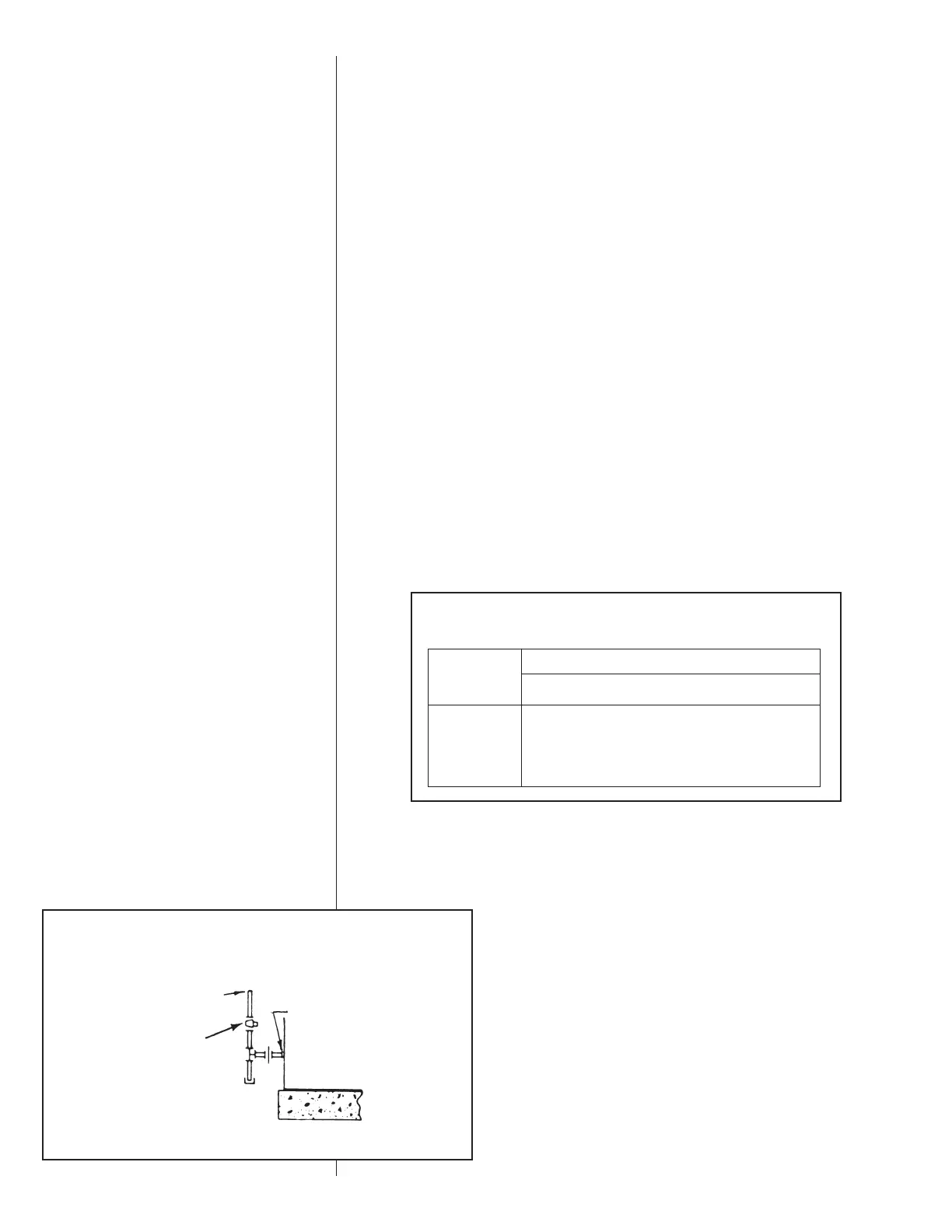
FIGURE 17
SUGGESTED GAS PIPING
FROM GAS
METER
*
Factory supplied grommet must be utilized.
MANUAL GAS
SHUT-OFF
VALVE
UNIT GAS SUPPLY
CONNECTION
*
ROOF OR GROUND LEVEL INSTALLATION
IMPORTANT: Disconnect the furnace and its individual shutoff valve from the gas
supply piping during any pressure testing of that system at test pressures in excess
of ½ pound per square inch gauge or isolate the system from the gas supply piping
system by closing its individual manual shutoff valve during any pressure testing of
this gas supply system at pressures equal to or less than ½ PSIG.
Nominal
Iron Pipe
Size,
Inches
Equivalent Length of Pipe, Feet
10 20 30 40 50 60 70 80
1
/2 132 92 73 63 56 50 46 43
3
/4 278 190 152 130 115 105 96 90
1 520 350 285 245 215 195 180 170
1
1
/4 1,050 730 590 500 440 400 370 350
1
1
/2 1,600 1,100 890 760 670 610 560 530
TABLE 1
GAS PIPE CAPACITY TABLE (CU. FT./HR. NATURAL GAS @ 0.30 IWC
[INCHES OF WATER COLUMN] PRESSURE DROP)
 Loading...