22
between separate devices which are eld installed and located, shall conform with
the temperature limitation for Type T wire [63°F rise (35°C)] when installed in accor-
dance with the manufacturer’s instructions.
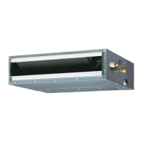
C. INTERNAL WIRING
A diagram of the internal wiring of this unit is located on the inside of control access
panel and in this manual. If any of the original wire as supplied with the appliance
must be replaced, the wire gauge and insulation must be same as original wiring.
Transformer and inducers are factory wired for 230 volts on 208/230 volt models and
must be changed for 208 volt applications. See unit wiring diagram for 208 volt wiring.
D. THERMOSTAT
The room thermostat must be compatible with the spark ignition control on the unit.
Generally, all thermostats that are not of the “current robbing” type are compatible with
the integrated furnace control. The low voltage wiring should be sized as shown in
Table 6.
Install the room thermostat in accordance with the instruction sheet packed in the
box with the thermostat. Run the thermostat lead wires through control entry opening
through the thermostat wiring chase on the unit (Figure 2 or Figure 21) and connect
to the low voltage thermostat connections (see wiring diagram). Never install the ther-
mostat on an outside wall or where it will be inuenced by drafts, concealed hot or
cold water pipes or ducts, lighting xtures, radiation from replace, sun rays, lamps,
televisions, radios or air streams from registers. Refer to instructions packed with the
thermostat for “heater” selection or adjustment.
See Thermostat Specication Sheet for recommended thermostats.
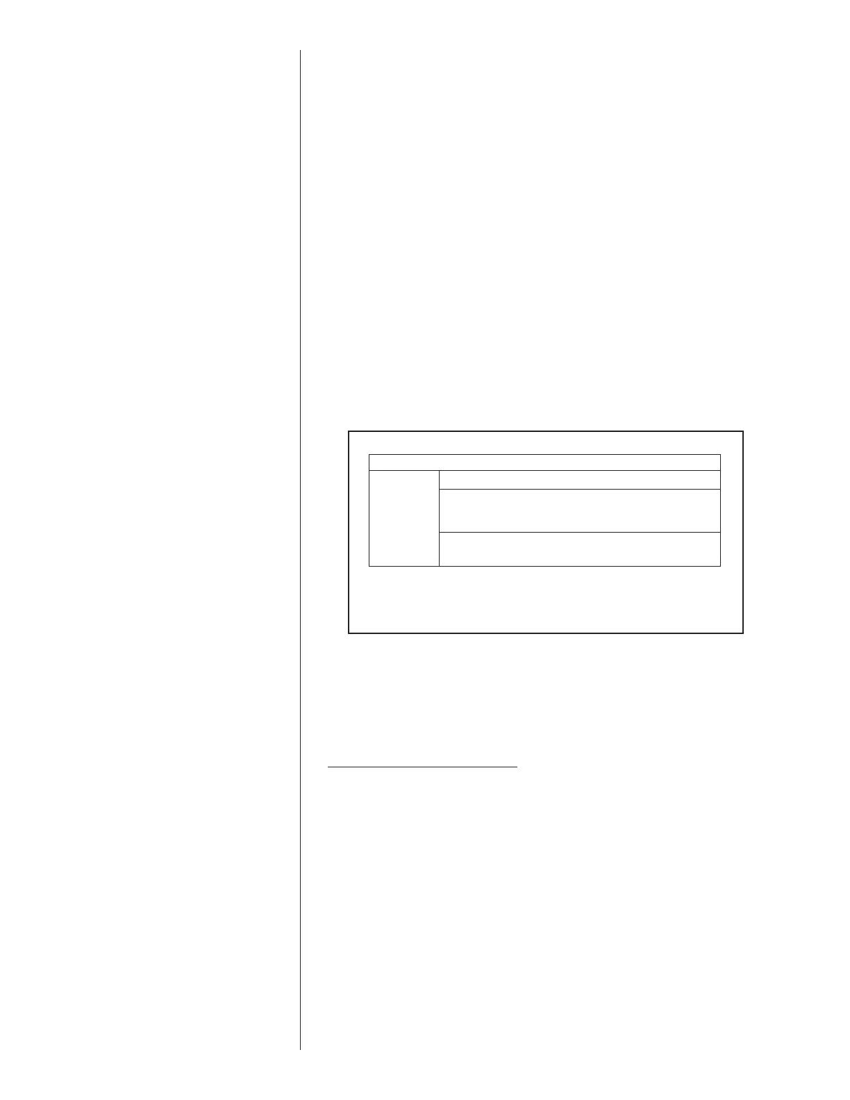
FIELD WIRE SIZE FOR 24 VOLT THERMOSTAT CIRCUITS
SOLID COPPER WIRE - AWG.
3.0 16 14 12 10 10 10
2.5 16 14 12 12 12 10
2.0 18 16 14 12 12 10
50 100 150 200 250 300
Length of Run – Feet (1)
Thermostat Load -
Amps
TABLE 6
(1) The total wire length is the distance from the unit to the thermostat
and back to the unit.
NOTE: DO NOT USE CONTROL WIRING SMALLER THAN NO. 18
AWG.
V. FURNACE SECTION CONTROLS AND
V. IGNITION SYSTEM
NORMAL FURNACE OPERATING SEQUENCE
This unit is equipped with a two stage integrated direct spark ignition control.
NORMAL HEAT MODE
A. Call For First Stage (low re) Only:
1. Zone thermostat contacts close, a call for rst stage (low re) heat is initiated.
2. Control runs self check.
3. Control checks the high-limit switch for normally closed contacts, each pressure
switch for normally open contacts, and all ame rollout switches for continuity.
4. Control energizes each low-re inducer.
5. Control checks each low-re pressure switch for closure.
6. If each low-re pressure switch is closed, the control starts a 30 second prepurge.
If either low-re pressure switch is still open after 180 seconds, the high-re induc-
ers will be energized until closure.
7. After prepurge timeout, control initiates spark for 2 seconds minimum, 7 second
maximum ignition trial, initiates 45 second, second stage (high re) warm up tim-
ing.
8. Control detects ame, de-energizes spark and initiates 45 second delay on blower
timing.
9. After a xed 45 seconds indoor blower delay on, the control energizes the indoor
blower.
10. After the 45 second second stage warmup period control checks thermostat input.
If only W1 is called for, W2 is de-energized and the control starts a 5 second off
delay on the W2 inducer.
11. After xed 5 seconds the W2 inducer is de-energized.
12. Control enters normal operating loop where all inputs are continuously checked.
 Loading...