ASSEMBLY
172 08/12 Assembly Section 3-6
© 2012 Alamo Group Inc.
ASSEMBLY
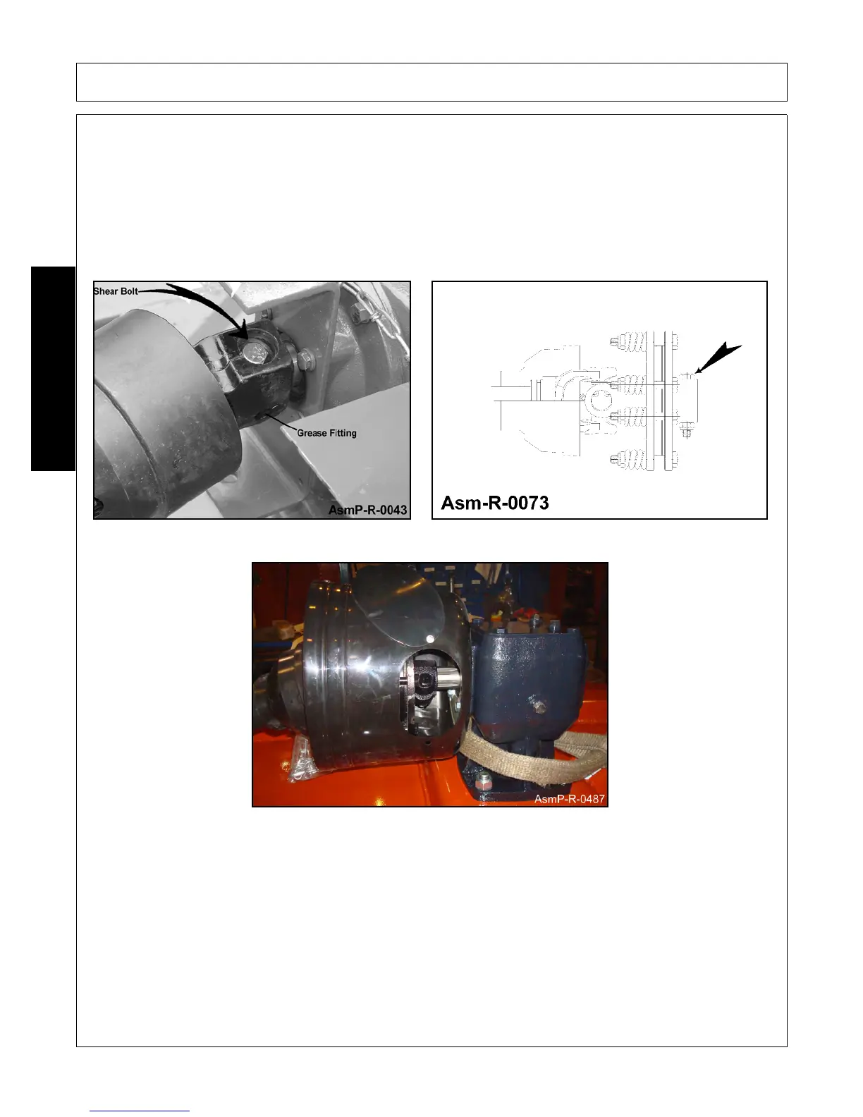
SHEAR BOLT or SLIP CLUTCH DRIVELINE INSTALLATION
Attach rear driveline of U-Joint to input shaft on gearbox, install snap ring in groove on input shaft.
NOTE: Check that Snap Ring is properly seated in groove. This snap ring retains driveline when shear bolt
shears. Install Grad 2 (Only) shear bolt 1/2” x 3-1/2”. Use of a stronger shear bolt other than Grade 2, will result
in driveline failure and will void warranty. Figure Asmp-R-0043
Attach slip clutch driveline to input shaft on gearbox with Grade 8 Bolt Figure Asm-R-0073 & AsmP-R-0487.
Refer to proper Torque Chart in Maintenance Section of this manual.
 Loading...