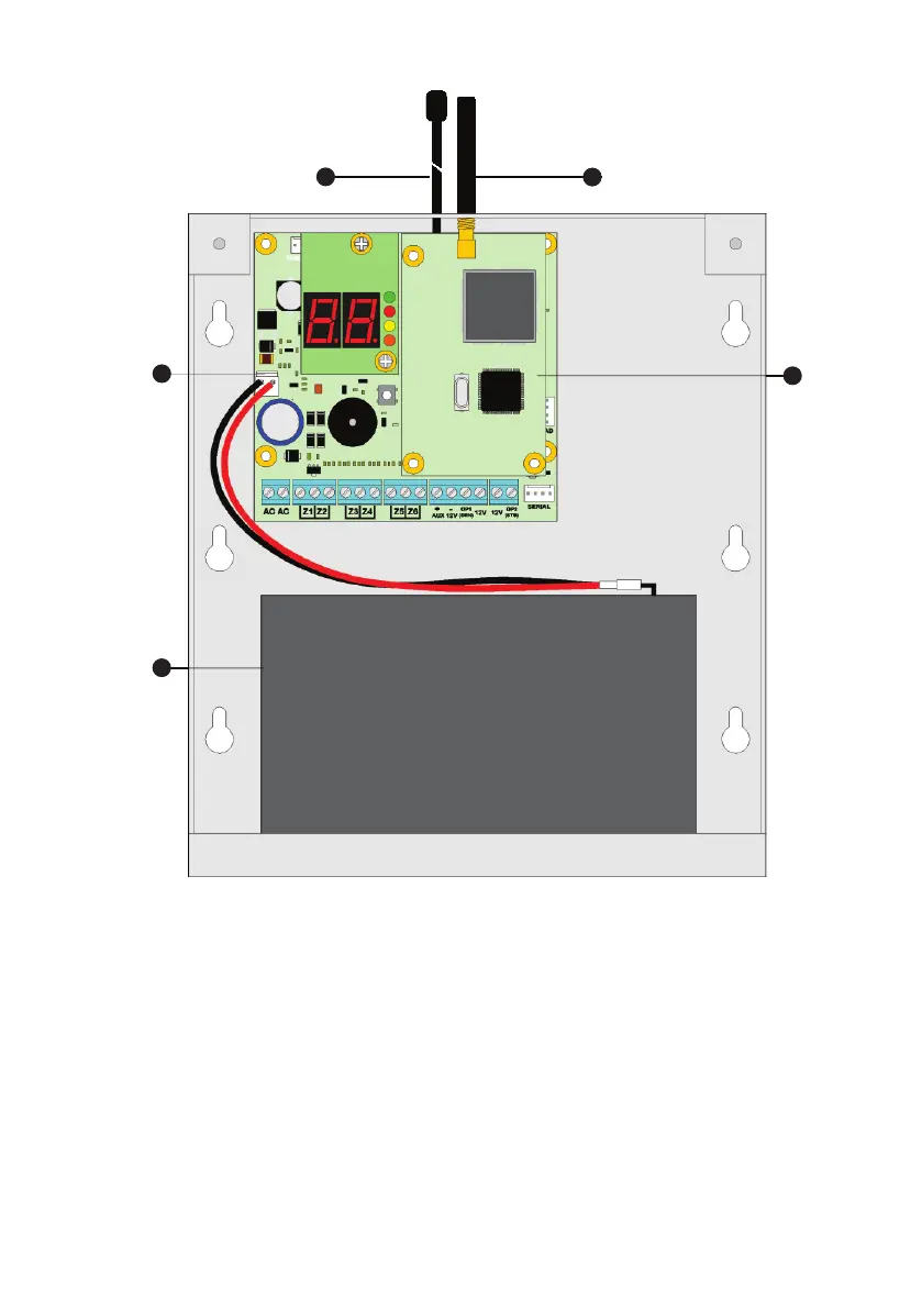
Panic Pack Layout
M ain Printed C ircuit Board (PCB)
5
3
4
1
2
1
The main PCB that provides the terminals connection to detection devices, see PCB Layout on the
next page for full details.
Standby Battery
2
The system housing will accept a 12V 7Ah battery to provide continued operation in the event of an
AC mains failure. Connect the red battery lead to the positive terminal of the battery and then
connect the lack battery lead to the negative terminal.
Rhino GSM Module
3
The Rhino GSM module must have a firmware of 1.48 or higher.
GSM Antenna
4
Screw in the GSM antenna.
Wireless Antenna
5
Screw in the wireless antenna for the onboard wireless transceiver.
7