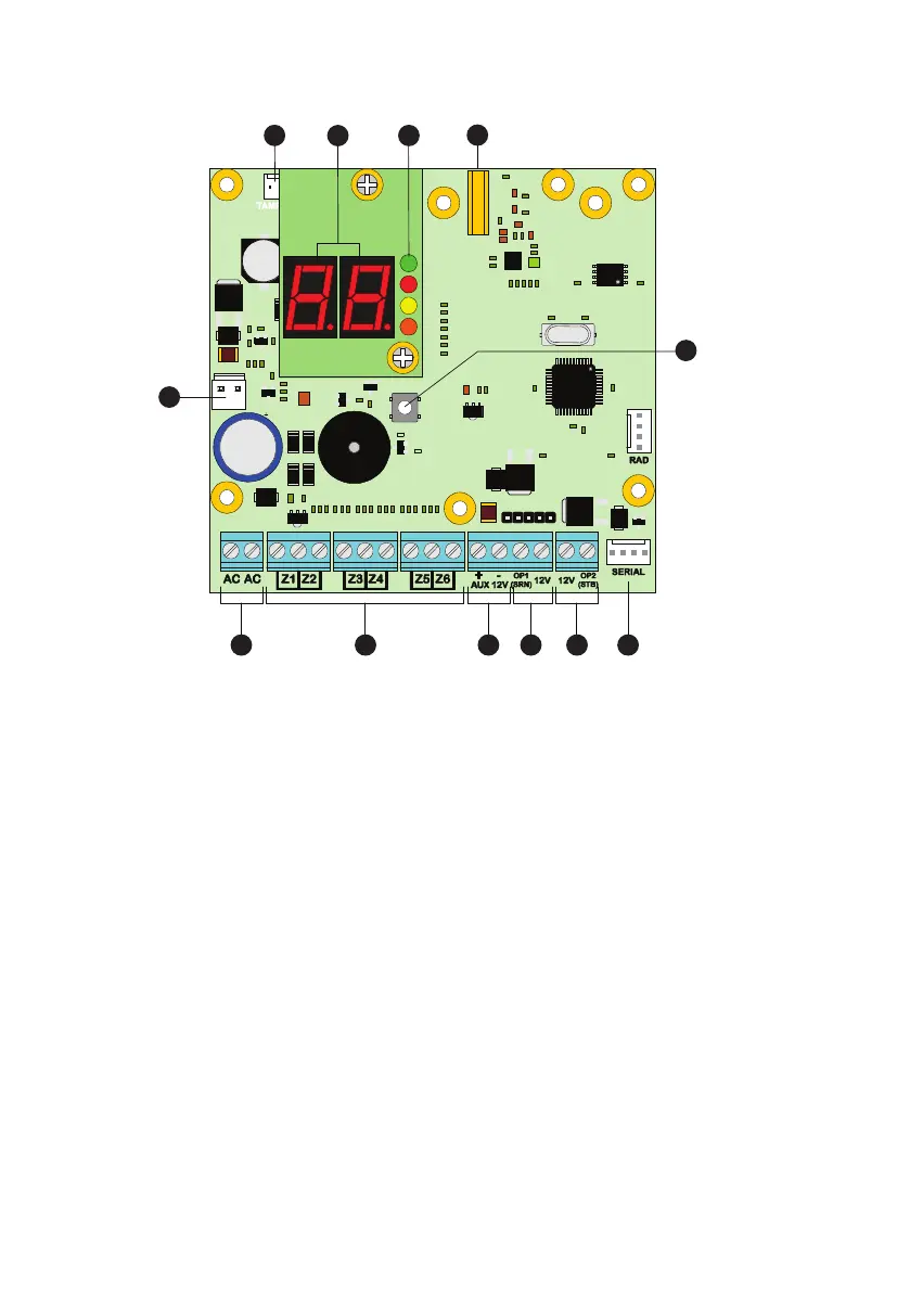
PCB L ayout
2. DedicatedE vent Trigger Inputs 1 to 6
The six inputs haved edicatedf uncons
i)
PanelO pen/CloseE vent
ii)
PanicB utton
iii)
Burglary Zone #1
iv)
Burglary Zone #2
v)
FireA larm
vi)
MedicalA l arm
3. Auxiliary 12V
These terminals provide auxiliary power for the external sounder
that might require 12V power. The auxiliary output is protected by
an autor esetng fuse (PTC) rateda t 1.1A mp).
4. Output 1
(Siren)
Output 1 is a high current (1 Amp),
switched negave supervised
output
for driving a siren/bell .
The funcon can be modified in the
configuraon.
5.O utput 2 (Strobe)
Output 2 is a high current (1 Amp), switched negave supervised
output for driving a strobe light.
The funcon can be modified in the
configuraon.
6. Serial
Port
The serial port
is providedf orl ocal downloading via Rhino
UDL.
7.R adio Serial Port
The Radio porti s used forc onnecngt o the serialc onnecon ont he
TX RhinoR adio Transmitter.
8. ModeB utton
This button performs several funcons:
a)
If the button
is held pressed during power up the control
will revertt od efault sengs.
b)
Aer power up, if the buttoni sp resseda nd held, itw ill
allow thel earning of a new Remote Control .
9. Antenna Screw Connector
This
connector provides a screw in connecon for the on -board
wireless transceiver antenna.
10.S ystem StatusL EDs
Green:
AC power present.
Red:
A Panic had beena cvated .
Yellow:
The Panic Packi si n FOB Learn Mode .
Orange:
Baery
Fault.
11. LED Status
display
Dual
red 7 segment LED display that shows Panic FOB informaon as
well as system
fault messages.
12. Lid T amper Connector
This connector can be used to connect a lid tamper switch to
providep rotecon for when the enclosure coveri so pened.
13. BatteryC onnecons
A 12V rechargeable baery must be connected to these two
terminals in order to provide connuous system operaon in the
event of mains failure. The baery output is protected by an auto
reseng fuse (PTC) rated at 1.6 Amp.
8
9
10
11
12
1 2
3 4 5 6
7
AC Input
1
The two wires from the transformer are connected to these terminals and supply power to the system.
Dedicated Event Trigger Inputs 1 to 6
2
The six inputs are normally open and triggered when they are closed. They have dedicated functions:
i) Panel open/close event
ii) Panic
iii) Burglary zone #1
iv) Burglary zone #2
v) Fire alarm
vi) Medical alarm
Auxillary 12V
3
These terminals provide auxiliary power for the external sounder that might require 12V power. The
auxiliary output is protected by an auto resetting fuse (PTC) rated at 1.1 Amp.
Output 1 (Siren)
4
Output 1 is a high current (1 Amp), switched negative supervised output for driving a siren/bell.
The function can be modified in the configuration.
Output 2 (Strobe)
5
Output 2 is a high current (1 Amp), switched negative supervised output for driving a strobe light.
The function can be modified in the configuration.
Serial Port
6
The serial port is provided for local downloading via Rhino UDL.
8