MAINTENANCE
SE6 05/05 Maintenance Section 5-14
© 2005 Alamo Group Inc.
MAINTENANCE
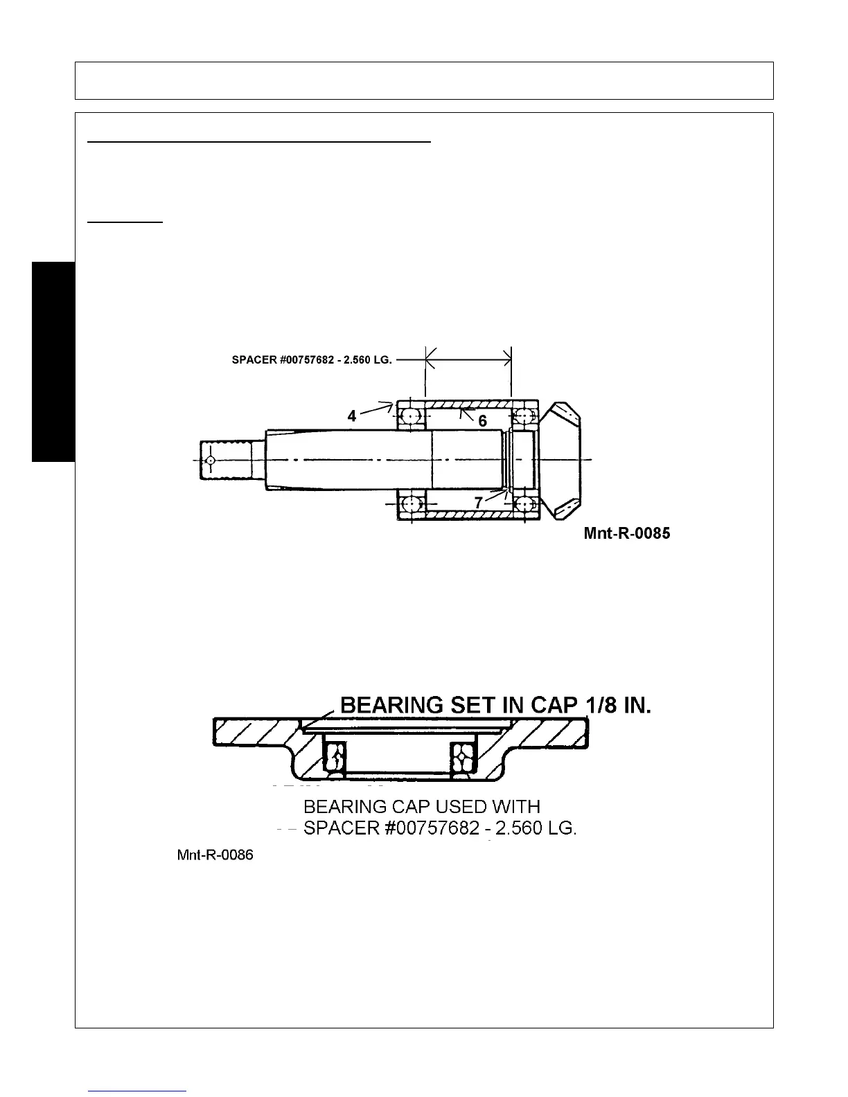
DISASSEMBLY OUTPUT SHAFT (Figure Mnt-R-0085)
1. Install slotted nut (Ref 19, Figure Mnt-R-0083, 5-11) onto shaft and then tap shaft end on a solid
surface to remove lower bearing and spacer.
2. Remove retaining ring (Ref #7) and then repeat above procedure to remove upper bearing.
ASSEMBLY
1. Assembly of output shaft is accomplished in exact reverse order. Install bearing over shaft and press
up against bottom end of gear. Install retaining ring (Ref. #7 Figure Mnt-R-0083).
2. Install spacer and lower bearing on shaft.
LOWER BEARING RETAINER CAP (Figure Mnt-R-0086)
1. Remove old seal from cap and press in new seal. (See SEAL INSTALLATION
RECOMMENDATIONS).
 Loading...