ASSEMBLY
TW6072 05/05 Assembly Section 3-2
© 2005 Alamo Group Inc.
ASSEMBLY
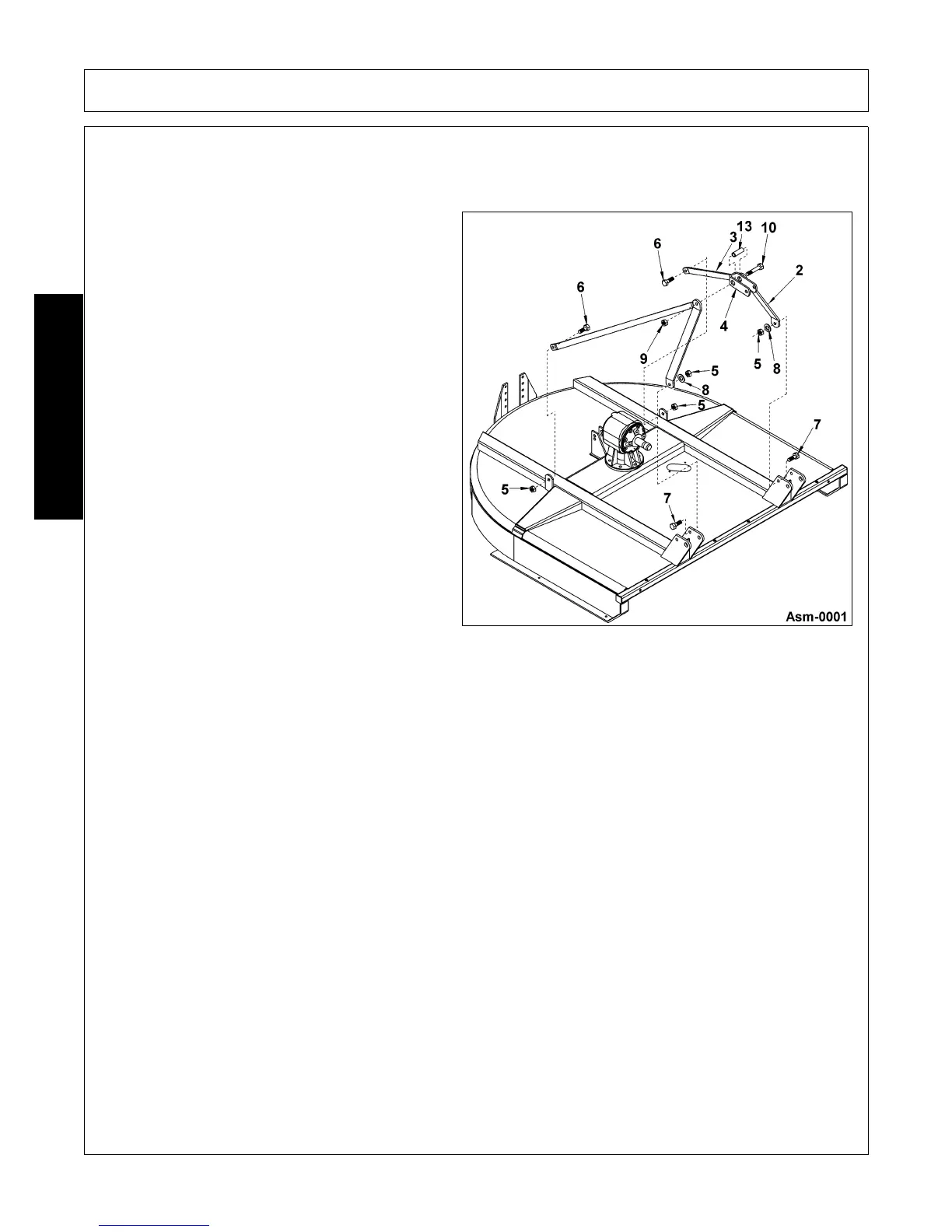
A-Frame Assembly (Figure Asm-0001)
To assemble the Mower’s A-Frame, follow the procedures listed below:
1. Place one rear brace (3) (end with smaller hole)
to the inside of each lift lug located in the mid
section of the mower on each side of the gear-
box. Position the braces so when attached to
the lugs, the braces bend towards the center of
the mower. Align the holes of the lugs and
braces and insert a 5/8” x 1-1/2” bolt (6) and
retain with a 5/8” locknut (5). Do not completely
tighten at this time.
2. One side at a time, position an A-frame leg (2)
to the inside of a inner lift lug located in the front
of the mower. The leg must be positioned with
the smaller hole to the bottom and the bend of
the leg to the center of the mower. Align the leg
hole and inner lug back hole and retain together
with a 5/8” x 2” bolt (7) and 5/8” flat washer (8)
and locknut (5). Repeat procedure for opposite
side.
3. Position bushing (13) within the toggle link (4)
back set of holes (holes closest to bend). Raise
rear braces (3) and position against each side
of toggle link and bushing. Raise A-frame legs
and position to the outside of each rear brace.
Insert a 3/4” x 6” bolt (10) through A-frame legs,
rear braces, toggle link, and bushing and retain
with a 3/4” locknut (9).
4. Tighten all bolts and locknuts per recom-
mended torque at this time.
 Loading...