INSTALLAZIONE
MECCANICA
Nell’installazione dei ventilconvet-
tori a sotto si consiglia di tener ben
presente il possibile problema di
straticazione dell’aria; ricordiamo
inoltre che le griglie di mandata de-
vono essere posizionate in modo
che la direzione del usso d’aria sia
verso il basso.
Installare l’apparecchio in una po-
sizione tale da non compromette-
re l’aspirazione dell’aria (vedi Pag.
11-12).
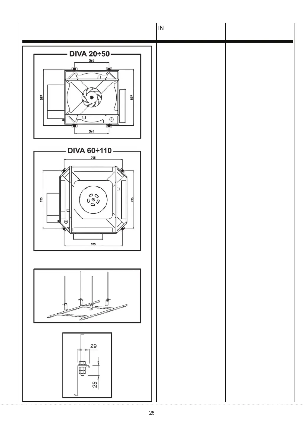
Fissaggio
del ventilconvettore:
Il ventilconvettore è ssato al sot-
to strutturale mediante barre let-
tate, non fornite.
I disegni mostrano la congurazio-
ne necessaria per ssare il ventil-
convettore in sede (vista dal pavi-
mento al sotto).
Procedura
La procedura per l’installazione del
ventilconvettore è la seguente:
• Marcare le posizioni dei fori nel
sotto strutturale in corrisponden-
za dei due lati opposti dell’aper-
tura praticata nel controsotto e
quindi praticare i fori per le barre
lettate (le dimensioni sono indi-
cate nei disegni a lato).
•
Fissare le barre lettate al sotto.
La lunghezza delle barre dipende
dallo spazio tra il controsotto e
il sotto strutturale.
MECHANICAL
INSTALLATION
When installing the fan coils on the
ceiling, keep in mind the possible
problem of strati cation of the air;
it should also be remembered that
the outlet grills must be positioned
so that the air ows downwards.
When positioning the appliance,
make sure the air intakes are free
from obstructions (see illustration
on Page 11-12).
Cassette xing:
The fan-coil unit is xed to the structural
ceiling by means of threaded rods
to be provided by others.
The drawings show the conguration
required for xing the fan-coil unit
into place (view from oor to ceiling).
Procedure
The procedure for installing the
fan-coil unit is as follows:
•
The hole positions in the structural
ceiling must rst be marked by
reference to the two opposite sides
of the cutout in the suspended
ceiling and the holes for the threaded
rods must then be drilled (dimensions
are shown by the drawings in this
page).
•
The threaded rods must then be
xed in the ceiling.
The length of the rods depends on
the clearance between the suspended
ceiling and the structural ceiling.