ELECTRONIC CONTROL FOR TERMINAL UNITS
12
II.3.2 CONNECTING THE POWER SUPPLY
Check that the voltage and frequency of the electrical system
correspond to 230V (± 10%) single phase at 50 / 60Hz, that the
installed power is sufficient for operation and that the cables of the
power supply line have a section suitable for the current maximum
request.
Make sure the electrical supply system complies with current National
safety regulations.
To connect the unit to the mains, use a two-pole + ground flexible cable,
section 1.5mm2 with a polychloroprene sheath of not less than H05RN-
F. The earth conductor must be longer than the other conductors in
order to ensure that if the cable fastening device should become slack,
it will be the last to be stretched.
The connections must be performed respecting the wiring diagrams.
(see A1 Wiring diagrams).
II.3.2.1 Connection of digital inputs (D1-D2-D3)
The connection between the board and the remote switch must be
carried out with a shielded cable consisting of 2 twisted conductors of
0.5 mm² and the shield (type Belden 8762 20 AWG). The screen must
be connected to the GND.
The maximum distance is 10m.
IMPORTANT!
Digital inputs between different boards can not be
connected in parallel. Use the clean contacts of an
external relay (not supplied).
II.3.2.2 Control panel connection (KPLT)
The connection between the board and the control panel must be
carried out with a shielded cable consisting of 2 twisted conductors of
0.5 mm² and the shield (type Belden 8762 20 AWG). The screen must
be connected on both sides to the GND.
The maximum distance is 100m.
II.3.2.3 Receiver connection (KRLT)
The connection between the board and the receiver must be carried out
with a shielded cable consisting of 2 twisted conductors of 0.5 mm² and
the shield (type Belden 8762 20 AWG). The screen must be connected
on both sides to the GND.
The maximum distance is 100m.
IMPORTANT!
The parallel connection of several motors to a
single 0-10Vdc analog output is forbidden
(AO-G terminals).
II.3.3 ADJUSTMENT FUNTIONS
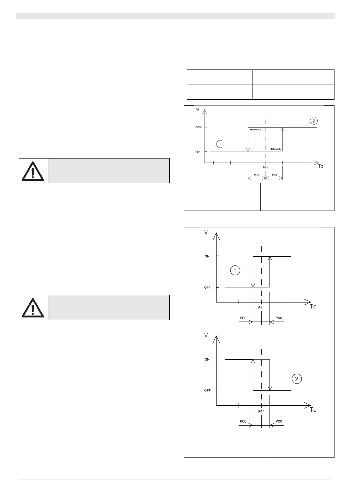
II.3.3.1 AUTO
In AUTO the terminal unit detects the room temperature and decides
which mode to activate (heating or cooling) based on the set point set
by the user, the mode is described in the graph below.
Mode Condition
Heating
Ta ≤ (P11 - P01)
Cooling
Ta ≥ (P11 + P01)
Not determined (P11 - P01) ˂ Ta ˂ (P11 + P01)
P01 = Neutral zone (2 ° C)
P11 = Set Point
Legend:
M = mode
Ta = temp. environment
1 = heating
2 = cooling
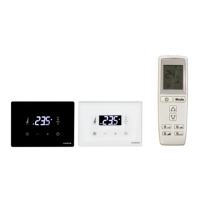
Once the mode is established, the control adjusts to the set point set
with differential P00:
P00 = Thermostat differential (0.2 °
C)
P11 = Set Point
Legend:
V = valve status
Ta = temp. Environment
1 = heating
2 = cooling