ELECTRONIC CONTROL FOR TERMINAL UNITS
19
II.3.5.7 LOCK FUNCTION
It allows a constrained management of the device in case of
applications managed centrally (constrained conditioning).
The function is enabled with the parameter LOC = 1.
In fact, it provides only the AUTO mode (or possibly EIR if enabled).
Para
meter
alue Description
LOC
0(*)
0 = Function not activated
1 = Function activated
(*) Default
The other possible functions:
turn off the unit;
varying the Set-points within a reduced interval (parameter SdE =
± 3 °);
vary the fan speeds (min-med-max-AUTO);
If the EIR function is active, the operating mode depends on the status
of the digital input.
The display is standard on the control panel (there is no active function
indication).
II.3.5.8 COMFORT CONTROL
±3°
In some installations the Set-point is decided
by the plant manager. In these cases, to
compensate for the different perception of
temperature, the user is given the opportunity
to increase or decrease the Set-point value.
The modification is made using the UP and
DOWN keys and is displayed for 2 seconds.
The function must be activated by setting the following parameters:
- Use the up / down keys to set the desired set point
- Change the SdE interval to the desired value (± 3 ° default)
- Change the parameter LOC = 2 (blocked set point)
Example: with set point at 22 ° C and SdE = 19 then the set point can
be modified within the range 22 ÷ 3 (3 ± 25 ° C).
Note: the range indicated by the SdE parameter has priority over the
min / max range (P23 / P24) of the set point.
Example:
set point range 15-30 ° C (P23 / P24)
set point set by keyboard 16 ° C
SdE = ± 3 °
LOC = 2
The set point can be changed between 13 ° (16-19) and 3 ° (3 + 16).
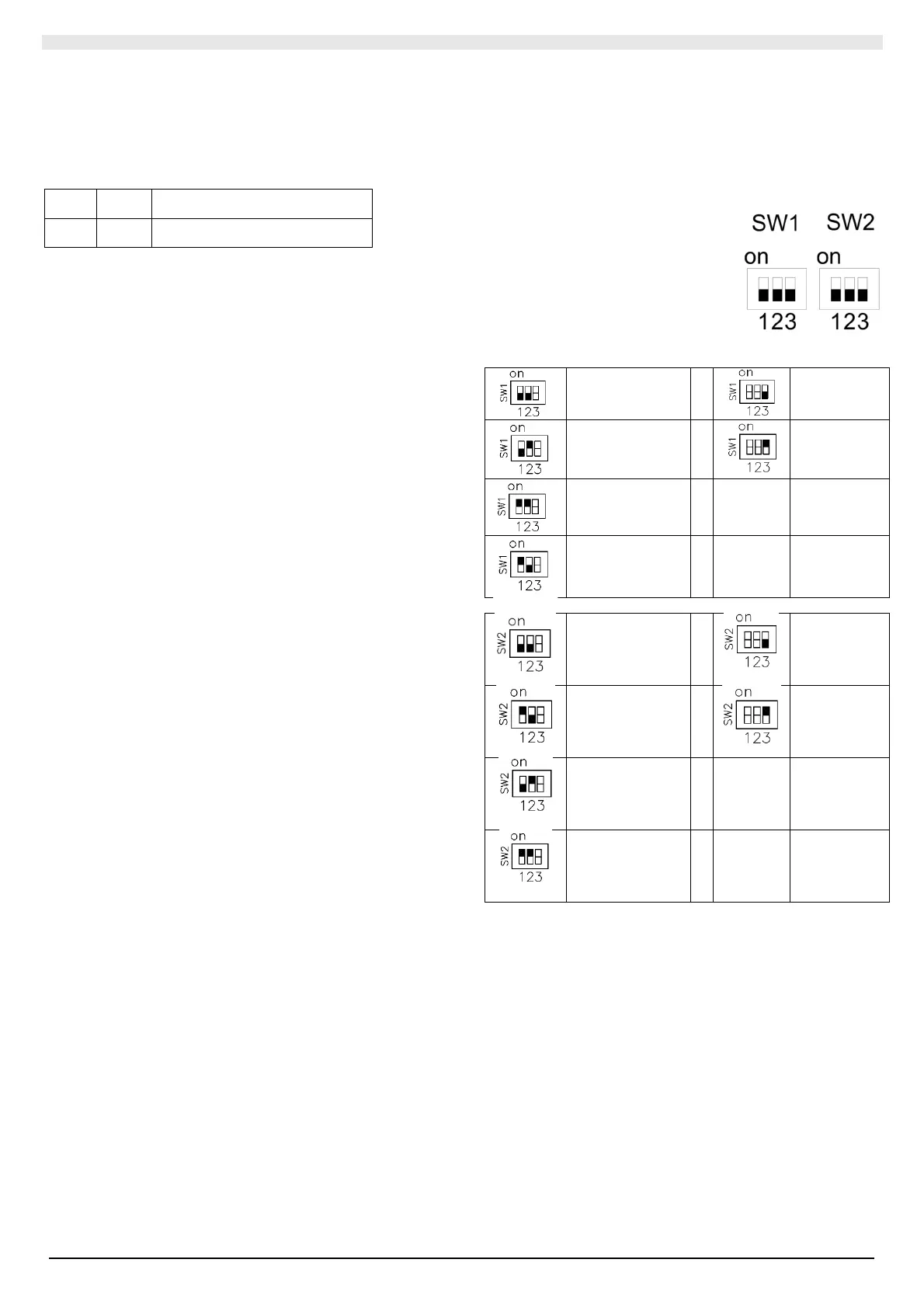
II.3.6 DIP-SWITCHES CONFIGURATIONS
Changes to DIP-Switches must be made when the board is powered
off.
The DIP-Switches on the control board can be switched using a sharp
implement. By following the instructions on the part and the table
provided below, it is possible to switch the DIP-Switches correctly.
Configuration set at the factory:
- 2tubi system
- AC motor (3 speed)
- speedometer x Yardy-I
- fancoil master
2-pipe system AC motor
AC motor
4-pipe system
EC motor
EC motor
2-pipe system +
res
2-pipe + radiant
system
Terna speed for
Yardy-I
P80=1Vdc
P81=6Vdc
P82=10Vdc
Fancoil Master
Terna speed for
Yardy-ID LOW
P74=2Vdc
P75=6,5Vdc
P76=8Vdc
Fancoil Slave
Terna speed for
Yardy-ID HIGH
P77=2Vdc
P78=7,1Vdc
P79=10Vdc
Terna speed for
DIVA-I
P86=1Vdc
P87=5Vdc
P88=10Vdc