ELECTRONIC CONTROL FOR TERMINAL UNITS
4
INDEX
I SECTION I :: USER .................................................................................... 5
I.1 Features ....................................................................................................................... 5
I.1.1 Declared conditions of use ............................................................................................ 6
I.1.2 Spare parts and accessories ......................................................................................... 6
I.2 Instructions for use ..................................................................................................... 7
I.2.1 Using the control panel.................................................................................................. 7
I.2.2 Unit in alarm condition ................................................................................................... 8
I.2.3 Using the remote control (KTLT) ................................................................................... 8
I.2.4 WALL RECEIVER (KRLT)............................................................................................. 9
I.2.5 RECEIVER on overlay for DIVA (KRLTI-KRLTM) ....................................................... 10
II SECTION II: INSTALLATION .................................................................. 11
II.1 Instruction for transport ........................................................................................... 11
II.1.1 Packaging and components ........................................................................................ 11
II.1.2 Handling guidelines ..................................................................................................... 11
II.1.3 Storage conditions ...................................................................................................... 11
II.1.4 Spaces of respect, positioning .................................................................................... 11
II.2 Installation instructions ............................................................................................ 11
II.3 Assembly of the Kit ................................................................................................... 11
II.3.1 Electrical connections ................................................................................................. 11
II.3.2 Connecting the power supply ...................................................................................... 12
II.3.3 Adjustment FUntions ................................................................................................... 12
II.3.4 Comfort functions ........................................................................................................ 16
II.3.5 Advanced features ...................................................................................................... 17
II.3.6 DIP-Switches configurations ....................................................................................... 19
II.3.7 auxiliary contacts of the KDO2 MODULE .................................................................... 20
II.3.8 SETTING AND MODIFICATION OF PARAMETERS WITH CONTROL PANEL ........ 20
II.3.9 SETTING AND MODIFICATION OF PARAMETERS WITH RECEIVER .................... 21
II.3.10 VISUALIZATION OF THE STATE OF THE UNITY ..................................................... 21
II.4 Instructions for start-up............................................................................................ 22
II.4.1 Preliminary checks before start-up .............................................................................. 22
II.4.2 Decommissioning ........................................................................................................ 22
II.4.3 Restart after prolonged shutdown ............................................................................... 22
II.5 Instructions for maintenance ................................................................................... 22
II.6 Indications for dismantling the unit......................................................................... 22
II.7 Troubleshooting ........................................................................................................ 23
ENCLOSED DOCUMENTS
A1 Electrical connections……………………………...……………………………….…24
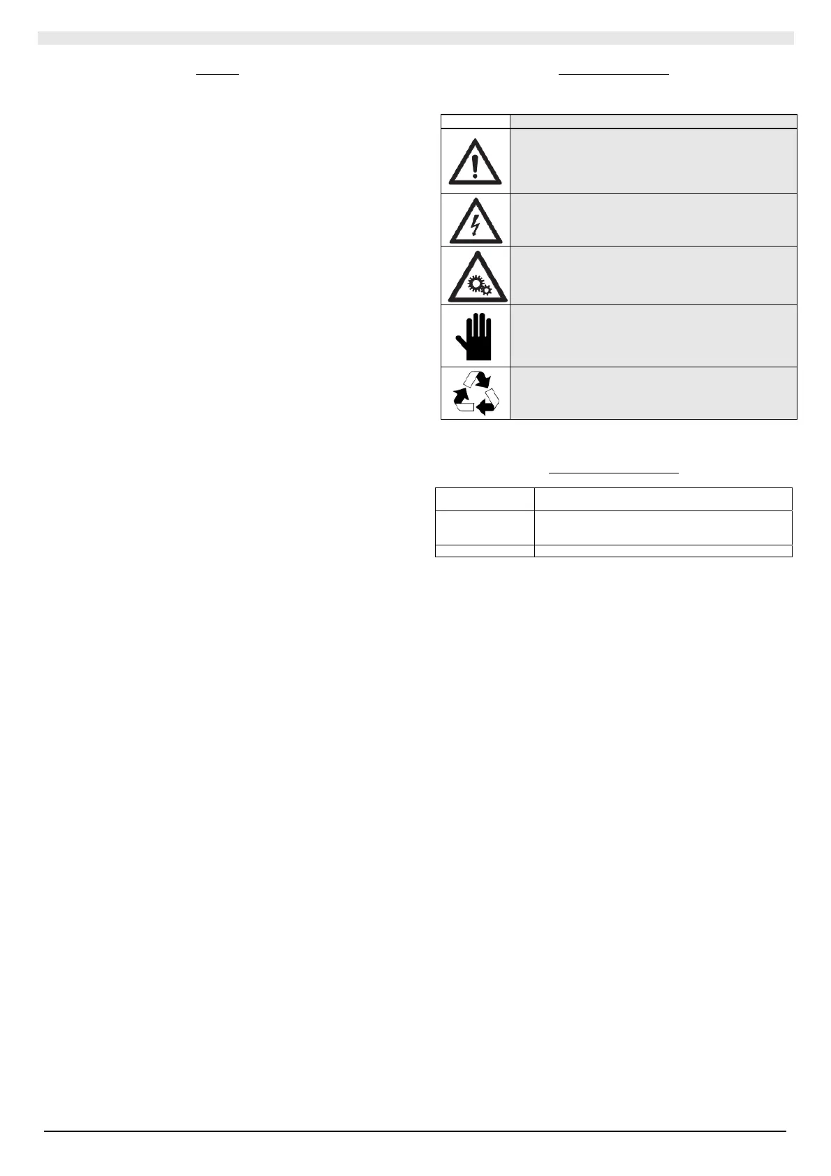
SYMBOLS USED
SYMBOL
MEANING
DANGER!
The DANGER sign warns the operator and
maintenance personnel about risks that may cause
death, physical injury, or immediate or latent
illnesses of any kind.
DANGER: LIVE COMPONENTS!
The DANGER: LIVE COMPONENTS sign warns the
operator and maintenance personnel about risks
due to the presence of live voltage.
DANGER: MOVING COMPONENTS!
The DANGER: MOVING PARTS sign warns the
operator and maintenance personnel about risks
due to the presence of moving parts.
IMPORTANT WARNING!
The IMPORTANT WARNING sign indicates actions
or hazards that could damage the unit or its
equipment.
SAFEGUARD THE ENVIRONMENT!
The environmental safeguard sign provides
instructions on how to use the machine in an
environmentally friendly manner.
Reference standards
CEI EN 60335-1
Sicurezza degli apparecchi elettrici d’uso domestico e
similare.
EN 50081-1:1992
Electromagnetic compatibility - Generic emission
standard Part 1: Residential, commercial and light
industry
EN 61000
Electromagnetic compatibility (EMC)