ELECTRONIC CONTROL FOR TERMINAL UNITS
16
II.3.4 COMFORT FUNCTIONS
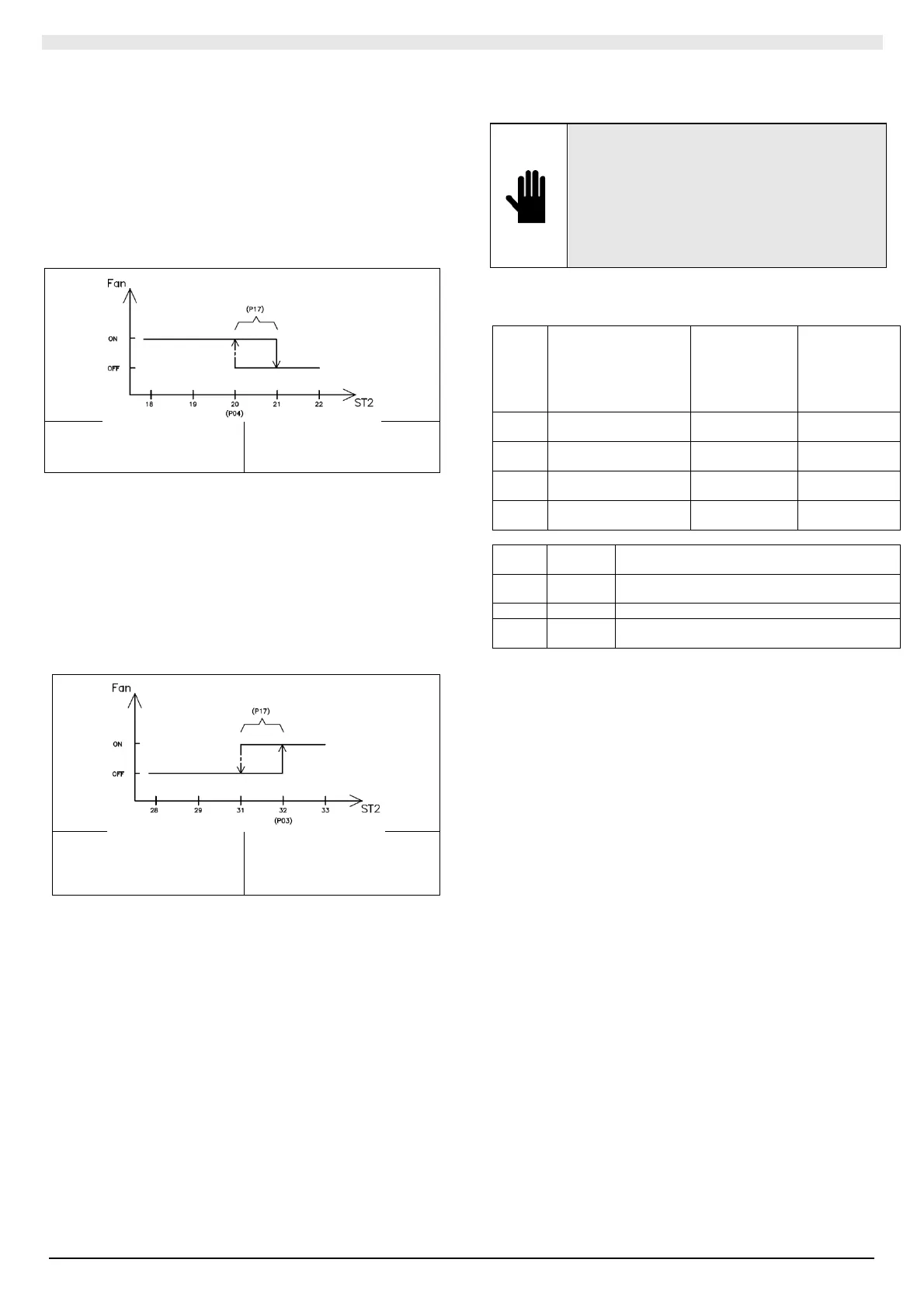
II.3.4.1 TOO COOL
For COOL operating mode, the TOO COOL function is provided, which
blocks the start of the fan if the temperature of the water entering the
exchanger is above 21 ° C (20 ° C set + 1 ° C of hysteresis) avoiding in
this way unpleasant flows of hot air.
This situation may occur when the unit is first started or after long stops.
The blinking of the fan LED indicates that the function is active.
Note: this function is only active in 2-pipe systems.
P04 = Too Cool water temperature
set point (20 ° C)
P17 = Hysteresis Water temperature
for Hot Start / Too Cool (1 ° C)
Legend:
Fan = fan status
ST2 = main exchanger temperature
(ST2 probe)
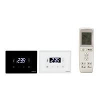
II.3.4.2 HOT START
For the HEAT functioning mode, the HOT START function is provided,
which blocks the start of the fan if the temperature of the water entering
the exchanger is below 31 ° C (32 ° C set + 1 ° C hysteresis) avoiding
this way unpleasant flows of cold air.
This situation may occur when the unit is first started or after long stops.
The blinking of the fan LED indicates that the function is active.
Note: in 4-pipe systems, the water probe is positioned on the hot
battery.
P03 = Hot Start water temperature
set point (32 ° C)
P17 = Hysteresis Water
temperature for Hot Start / Too Cool
(1 ° C)
Legend:
Fan = fan status
ST2 = main exchanger temperature
(ST2 probe)
II.3.4.3 PERIODIC VENTILATION / CONTINUED
IMPORTANT!
To counteract the air stratification phenomenon, the
terminal unit performs fan on / off cycles at
minimum speed, even when the room temperature
has reached the set point (the hot / cold valve
remains closed). This contributes to a correct
detection of the ambient temperature if the probe of
the KPLT terminal (control probe ST1) is not used. If
the regulation is carried out with the probe of the
KPLT terminal, the function is disabled.
It is possible to define the behavior of the fan when the temperature
value set in the hot and cold mode is reached:
Para
meter
Description Default values
with panel on
board, with
KRLT and with
KRLTI /
KRLTM
Default values
with KPLT
wall panel
P19
Fan on time in HEAT
(min)
1 0
P20
Fan time off in HEAT
(min)
20 0
P21
Fan time on in COOL
(min)
1 0
P22
Fan time off in COOL
(min)
20 0
P19
P21
P20
P22
Set point fan reached
≠0 ≠0 The fan performs periodic ventilation at
minimum speed respecting the set on / off times.
0 any Fan is always off
≠0 0 Fan is always on at the set speed (in AUTO at
minimum speed)
Note: if the continuous fan speed is set, the use of the water valve is
mandatory.
II.3.4.4 MEMORY
After a power failure, the appliance will resume operation in the way it
was at the time the interruption occurred.
MEMORY is also active in the remote control and SECURITY control
ON / OFF functions.