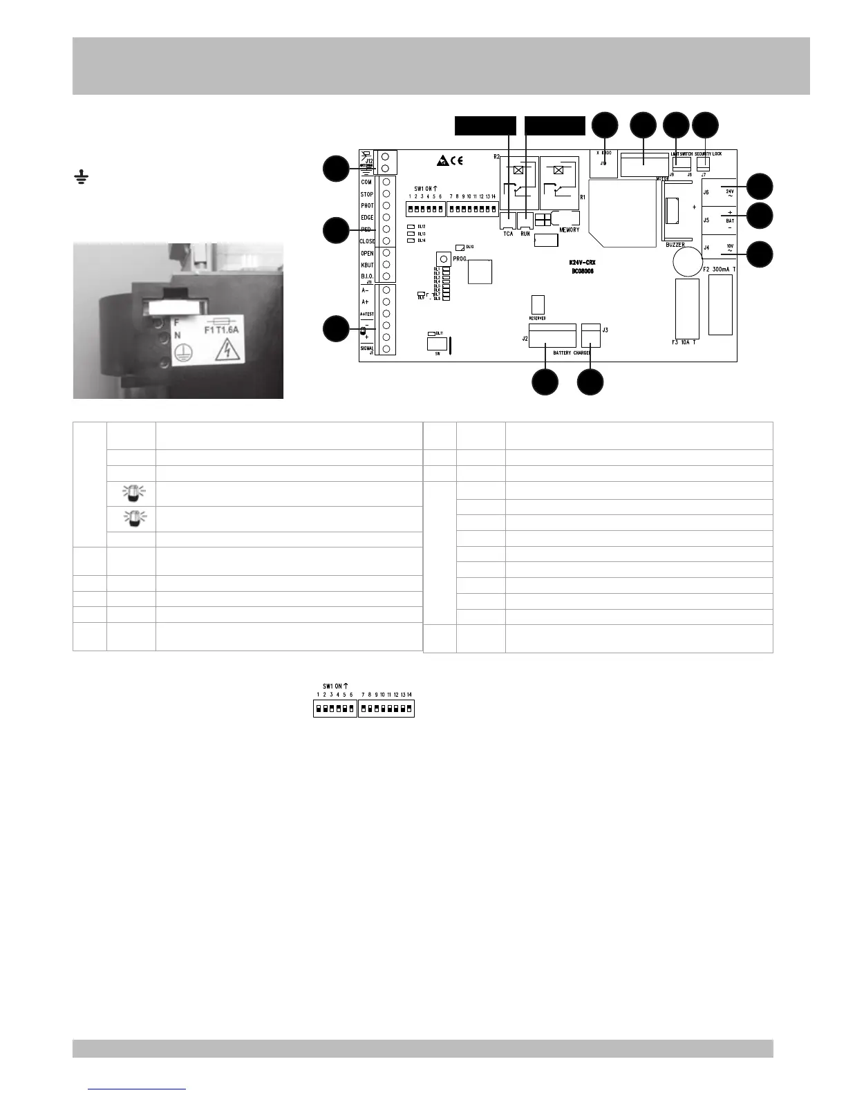
POINT A - ELECTRIC CONNECTIONS
G
B
B – SETTINGS
DIP 1 adjust stroke in line with electrical or magnetic limit
switches (point C)
DIP 2 programme full opening (point D)
DIP 2-1 programme pedestrian opening times (point E)
DIP 1-2 save/delete radio codes for full opening control (point F)
DIP 1-2 save/delete radio codes for pedestrian opening control (point G)
CONTROL MICRO-SWITCHES
DIP 3
ON - gradual start enabled
OFF - gradual start disabled
DIP 4
ON - photocells enabled only when closing
OFF - photocells always enabled
DIP 5
ON - heater enabled
OFF - heater disabled
DIP 6
ON - radio, k butt button and pedestrian control enabled in automatic mode
OFF - radio, k butt button and pedestrian control enabled in step-by-step mode
DIP 7
ON - current sensor enabled
OFF - current sensor disabled
DIP 8
ON - instant re-closing after transit on enabled photocell
OFF - instant re-closing after transit on disabled photocell
DIP 9
ON - mode on always, even with remote control enabled
OFF - mode on always, even with control buttons enabled
DIP 10
ON - edge auto-test enabled
OFF - edge auto-test disabled
DIP 11
ON - pre-flashing enabled
OFF - pre-flashing disabled
DIP 12
ON - available
OFF - available
DIP 13
ON - function dedicated to gear motor K800
OFF - function dedicated to gear motor K400
DIP 14
ON - enable SUN/MOON radio system
OFF - enable SUN-PRO radio system
PROG. > PROGRAMMING KEY.
MEMORY > EXTRACTIBLE MEMORY CONTAINING FUNCTIONAL DATA AND RADIO
CODES.
SW > CONNECTOR FOR SOFTWARE UPGRADE.
J1 A- COMMON WIRE OF ACCESSORIES POWER SUPPLY AND EDGE AUTO-
TEST
A+ POSITIVE FOR 24Vdc POWER SUPPLY TO ACCESSORIES
A+ TEST POSITIVE FOR 24Vdc POWER SUPPLY TO EDGE AUTO-TEST
-
NEGATIVE FLASHER 24Vdc 20W
+
POSITIVE FLASHER 24Vdc 20W
SIGNAL OPEN GATE INDICATOR 24 Vdc MAX 10 W
J2-J3 BATTERY
CHARGER
CONNECTORS FOR BATTERY CHARGER BOARD (CODE ACG4667
OPTIONAL)
J4 10V CONNECTORS FOR SECONDARY 10 VAC TRANSFORMER
J5 BAT BATTERY CONNECTORS (OPTIONAL)
J6 24V CONNECTORS FOR SECONDARY 24 VAC TRANSFORMER
J7 SECURITY
LOCK
CONNECTOR FOR MANUAL RELEASE SWITCH
J8 LIMIT
SWITCH
CONNECTOR FOR ELECTRICAL OR MAGNETIC LIMIT SWITCHES
J9 MOTOR CONNECTOR FOR 24Vdc MOTOR AND 5VDC ENCODER
J10 X K800 CONNECTORS FOR MOTOR K800 CONNECTION (DO NOT USE)
J11 COM CONTACTS COMMON WIRE (GND)
STOP STOP PULSE CONTACT (NC)
PHOT PHOTOCELLS CONTACT (NC)
EDGE EDGE CONTACT (NC)
PED PEDESTRIAN OPENING PULSE CONTACT (NO)
CLOSE CLOSE PULSE CONTACT (NO)
OPEN OPEN PULSE CONTACT (NO)
KBUT SINGLE PULSE CONTACT (NO)
B.I.O. CONTACT (NO) DEDICATED TO A CLOCK
J12 ANTENNA TERMINALS DEDICATED TO CONNECTION OF A 433.92 MHz
ANTENNA
J12
J6
J8J9
J2
J10 J7
J3
J5
J4
J11
J1
Trimmer TCA Trimmer RUN
EXTERNAL MAINS POWER SUPPLY TO BOARD 230 Vac
50/60 Hz (120 Vac 60 Hz on request)
F > PHASE
N > NEUTRAL
> EARTH
F1 T1,6A FUSE ON MAIN POWER TERMINAL