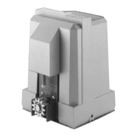
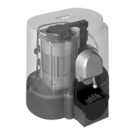
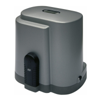
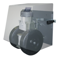
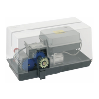
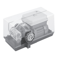
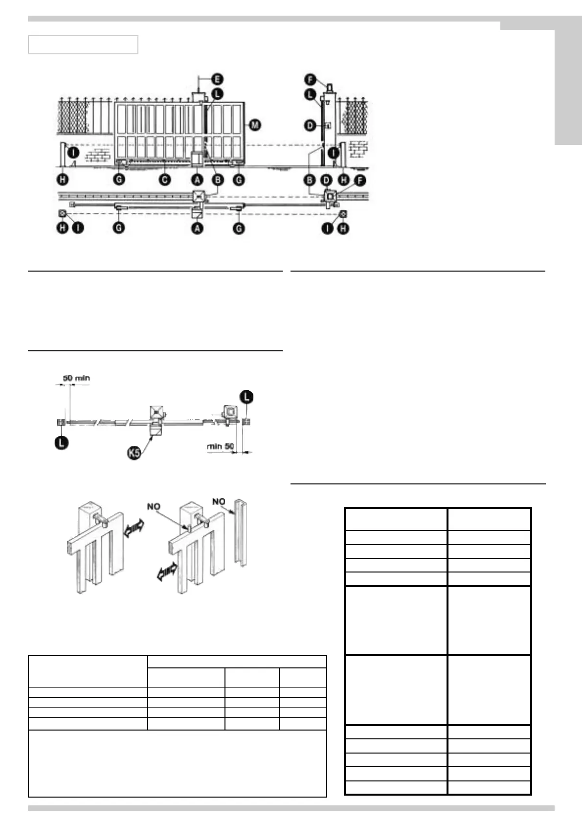
A - K5 operator
B - Photoelectric cells (external)
C - Rack
D - Key selector
E - Tuned aerial
F - Flashing lamp
G - Limit switch cam
L - Mechanical strip
M - Pneumatic strip
Fig. 1
Fig. 2
SYSTEM LAY-OUT
CHECKING BEFORE THE INSTALLATION
!! THE GATE SHALL MOVE FRICTIONLESS !!
N.B.: Gate features must be uniformed with the standards and laws in force. The
door/gate can be automated only if it is in a good condition and its conditions comply
with the EN 12604 norm.
- The door/gate leaf does not have to have a pedestrian opening. In the opposite case it
is necessary to take the appropriate steps, in accordance with EN 12453 norm (for
instance; by preventing the operation of the motor when the pedestrian opening is
opened, by installing a safety microswitch connected with the control panel).
- Besides the electrical or mechanical limit switches available on the operators, there
must be, on both ends of the installation, a fixed mechanical stopper which stop the
gate in the unlikely event of ill functioning of limit swithces on the operators. For this
reason the fixed mechanical stopper must be of an adeguate size to withstand the
static and kinetic forces generated by the gate (12) (Fig.2).
The guide must be provided with two mechanical stops at its ends (12) (Fig. 2).
Gate columns shall have anti-derailment guides on their top (Fig. 3), to avoid the
unintentional gate release.
N.B.: Eliminate those mechanical stops of the kind described by figure 3.
No mechanical stop shall be on top of the gate, since mechanical stops are not safe
enough.
TECHNICAL FEATURES
Irreversible operating devices for sliding gates with a maximum weight of 500
Kg/1100lbs.
The irreversibility of this operating device allows you to avoid using any electric lock for
an effective closing of the gate. The motor is protected by an heat probe, that temporary
interrupts the operating cycle in case of prolonged use.
TECHNICAL
DATA
Max. leaf weight
EEC Power supply
Motor capacity
Power absorbed
Capacitor
No. cycles
Weight of electroreducer
Protection
Noise
Working temperature
Operating speed
Thrust force
Grease
Rack
K5
500Kg-1100lbs
0,160m/sec - 31,5 ft/min
N 360
4
230V~ 50/60Hz
W 206
A 0,93
µF8
n° 10 - 30s/2s
Bechem - RHUS 550
8Kg - 17,6lbs
db <70
°C -10 ÷ +55°C
IP 54
Power supply
Motor capacity
Power absorbed
Capacitor
No. cycles
120V~ 60Hz
W 170
A 1,9
µF60
n° 27 - 30s/2s
COMMAND TYPE USE OF THE SHUTTER
Skilled persons Skilled persons Unrestricted use
(out of a public area*) (public area)
with manned operation A B
with visible impulses (e.g. sensor) C C C e D
with not visible impulses (e.g. remote control device)
C C e D C e D
automatic C e D C e D C e D
* a typical example are those shutters which do not have access to any public way.
A: Command button with manned operation (that is, operating as long as activated), like code
ACG2020.
B: Key selector with manned operation, like code ACG1010.
C: Safety edges or Sensor able to detect an obstacle and/or other safety devices to keep thrust force
within the limits of EN12453 regulation - Appendix A.
D: Photocells, like code ACG8026.
Parts to install meeting the EN 12453 standard
Pag. 19 di 36
Fig. 3
E
N
G
L
I
S
H
 Loading...