22
22
GG
BB
PRE-INSTALLATION CHECKS
The leaf must be fixed firmily on the hinges to the pillars, must not be
flexible during the movement and must move without frictions.
Before the installation of KING, verify all dimensions etc.
There's no need for any modification, if the gate is like that shown in
Fig. 1.
Gate features must be uniformed with the standards and laws in
force. The gate can be automated only if it is in a good condition and
its conditions comply with the EN 12604 norm.
- The gate leaf does not have to have a pedestrian opening. In the
opposite case it is necessary to take the appropriate steps, in
accordance with EN 12453 norm (for instance; by preventing the
operation of the motor when the pedestrian opening is opened, by
installing a safety microswitch connected with the control panel).
- No mechanical stop shall be on top of the gate, since mechanical
stops are not safe enough.
FIXING THE ACTUATOR ATTACHMENT TO THE COLUMN
To obtain a correct movement of the leaf gate it is necessary to respect
the measures (to see the TABLES of the measures).
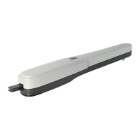
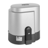
COLUMN ATTACHMENT FOR KING OPERATOR
(code CCA1293 - CCA1294)
If the column is in iron, the attack can be screwed directly using four
metric screws M8.
If the column is in concrete, the attack can be fixed with four expansion
screws Ø 8 mm (Fig. 2-3).
In the case you have a wall parallel with the open gate, you must
provide a niche in which to place the operator.
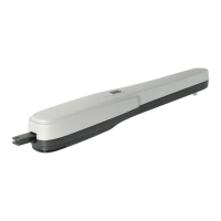
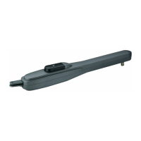
COLUMN ATTACHMENT FOR KING L OPERATOR
(code CCA1370 - CCA1319)
To obtain a correct movement of the leaf gate it is necessary to respect
the measures.
If there is an iron pillar you can weld the attachment directly
.
If there is a cement pillar, you can use the fixing plate as in Fig. 5 which
is fastened with 4 Fischer-screws of Ø 8 mm.
There is also the possibility to cement the attachment welding an
anchor at its base Fig. 6.
Naturally you have to respect predetermined fixing measures.
Afterwards you must weld the other actuator's attachment to the gate
(Fig. 8).
In the case you have a wall parallel with the open gate, you must
provide a niche in which to place the operator.
2
4
76
5
3
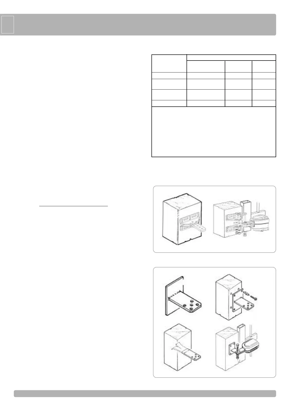
INSTALLATION KING
COMMAND TYPE USE OF THE SHUTTER
Skilled persons Skilled persons
Unrestricted use
(out of public area*) (public area)
with manned operation A B non possibile
with visible impulses
C or E C or E C and D, or E
(
e.g. sensor)
w
ith not visible impulses
C or E C and D, or E C and D, or E
(
e.g. remote controldevice)
automatic C and D, or E C and D, or E C and D, or E
* a typical example are those shutters which do not have access to any public way
A: Command button with manned operation (that is, operating as long as activated),
like code ACG2013
B: Key selector with manned operation, like code ACG1010
C: Adjustable power of the motor
D: Safety edges, like code ACG3010 and/or other safety devices to keep thrust
force within the limits of EN12453 regulation - Appendix A.
E: Photocells, like code ACG8026 (To apply every 60÷70cm for all the height of the
column of the gate up to a maximum of 2,5m - EN 12445 point 7.3.2.1)
Parts to install meeting the EN 12453 standard