EasyManua.ls Logo

RIB RAPID N - User Manual

RIB RAPID N
80 pages
Go to English
Print Icon
To Next Page IconTo Next Page
Loading...
ITALIANO pag. 05 / FRANÇAIS pag. 19 / ENGLISH page 33 / DEUTSCH pag. 47 / ESPAÑOL pag. 61
RAPID N
c P1-CRX
Vedere pagina 18
Voir page 32
See page 46
Siehe Seite 60
Ver página 74
Operatore
Operateur
Operator
Torantrieb
Operador
Alimentazione
Alimentation
Power Supply
Stromspannung
Alimentacion
Lunghezza max asta
Longueur maxi de la lisse
Max. boom lenght
Max. Baumlänge
Longitud máxima de la asta
Codice
Code
Code
Code
Codigo
RAPID N
230V/50-60Hz 3 ÷ 6 m
AA50140
RAPID N METAL AA50142
EL PRODUCTO SE ENTIENDE PARA EL CONTROL DE TRÀFICO VEHICULAR,
Y NO PARA TRÀFICO PEATONAL.
Aconsejamos, por lo tanto, aplicar las seguridades requeridas y
carteles como art. ACG9624, para que los peatones no choquen con
el producto.
QUESTO PRODOTTO È DEDICATO AL CONTROLLO DEL TRAFFICO
VEICOLARE, NON A QUELLO PEDONALE.
Si consiglia pertanto l’applicazione delle sicurezze richieste e di uno
o più cartelli di attenzione cod. ACG9624 per evitare il contatto dei
pedoni con il prodotto.
CE PRODUIT EST DÉDIÉ AU CONTRÔLE DU TRAFIC VÉHICULAIRE, ET NON À CELUI
DES PIÉTONS.
Il est donc conseillé d’appliquer les règles de sécurité demandées et de
signaler le danger par un ou plusieurs panneaux ACG9624 afin d’éviter tout
contact entre les piétons et le produit.
THIS OPERATOR IS DESIGNED FOR THE VEHICLES ACCESS CONTROL
AND NOT FOR PEDESTRIANS.
Therefore, we higly recommend the use of safety devices and that of
one or more warning plates, art. ACG9642 to prevent the pedestrians
interfering with the operator.
DAS PRODUKT IST ZUR KONTROLLE VON WAGENVERKEHR, NICHT VON
FUSSGÄNGER- GEMEINT.
Wir weisen darauf hin, die geforderten Sicherheitszeichen, wie per
Art.-Nr. ACG9624 anzuhängen, um den Kontakt zwischen Fussgänger
und Produkt zu vermeiden.
Disegni tecnici per progetti
Dessins techniques pour les projets
Technical drawings for projects
Technische Zeichnungen für Projekte
Dibujos técnicos para proyectos.
Question and Answer IconNeed help?

Do you have a question about the RIB RAPID N and is the answer not in the manual?

Overview

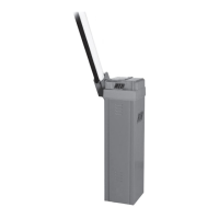
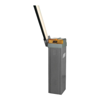
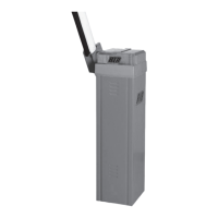
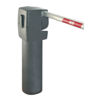
The RIB RAPID N P1-CRX is an ambidextrous, irreversible operator with an integrated control panel, designed for intensive movement of boom arms ranging from 3 to 6 meters long. The operator's cabinet is treated with cataphoresis and a thermal spray coating for durability. The barrier boom can be supplied as a single piece or, for situations where high objects might obstruct its travel, an articulated version can be requested, with the obstacle height from the ground specified. The RIB profile boom is designed to accommodate a photocell strip. It is crucial that all installation features comply with applicable laws and standards.

Technical Specifications:

  • Max. boom length: 6 meters (236 inches)
  • Opening time: 6 seconds
  • EEC Power supply: 230V~50Hz (220V~60Hz available upon request)
  • Motor capacity: 242 W (285 W for 220V~60Hz)
  • Power absorbed: 1.07 A (1.31 A for 220V~60Hz)
  • Capacitor: 10 µF (10 µF for 220V~60Hz)
  • Max. torque: 155 Nm (141 Nm for 220V~60Hz)
  • Normative cycles: 2400 - 6s/2s
  • Daily operations suggested: 1500 for boom 3-4-5-6 m
  • Service: 100%
  • Guaranteed consecutive cycles: 1500 for boom 3-4-5-6 m
  • Lubrication: SHELL OMALA S2 G100
  • Weight of electroreducer: 62 kg
  • Working Temperature: -10 ÷ +55 °C
  • Protection IP: 54

Control Panel Features:

The control panel includes various connections and settings for comprehensive management of the barrier.

  • Power Supply (L-N): 230 Vac 50/60Hz (120 Vac 60 Hz upon request).
  • Motor Connections (U-MOTOR, V-W-MOTOR): Common motor, phases, and capacitor connections.
  • Flashing Light: Max 40W output.
  • PROBE (J3): Terminal for connecting a heater probe (optional ACG4666) for cold climates.
  • Radio Module (J4, J5, J6): Connectors for radio module ACG8069 and RIB receiver, with 24Vdc supply and 433 MHz antenna.
  • APP+ Card (J9, J10): Connectors for APP+ and APP cards.
  • Serial Communication (J11): Connector for serial communication.
  • Auxiliary Relay (R-AUX, J12): NO contact, Max 700 W, for courtesy light or boom arm locking magnet.
  • Gate Open State (SIGN. -, SIGN. +, J12): 12 Vdc 3 W max warning light.
  • Common Contacts (COM A+, J13, J14, J15): Positive 24 Vdc for various contacts.
  • Stop Impulse (STOP, J13): NC contact.
  • Photocells (PHOTO 1, PHOTO 2, J13): NC contacts for photocells 1 and 2.
  • Edge Contact (EDGE, J13): NC contact for safety edge.
  • Vehicle Presence Signal (TLC, J13): NO contact, only in PARK mode.
  • Limit Switches (LSC, LSO, LSSC, LSSO, J14): NC contacts for closing/opening limit switches, and NO contacts for slowing down in closing/opening.
  • Immediate Closure (OK CLOSE, J15): Contact for immediate closure, only in PARK mode.
  • Timer (B.I.O., J15): NO contact for a dedicated timer.
  • Single Pulse (START, J15): NO contact.
  • Closing Impulse (CLOSE, J15): NO contact.
  • Opening Impulse (OPEN 1, OPEN 2, J15): NO contacts for entering/exiting in PARK mode.
  • A+TEST (J16): Positive 24Vdc for photocells self-test.
  • CARD AUX (J17): Connectors for 1-relay (ACQ9080) or 3-relay (ACQ9081) cards for courtesy light, boom arm locking magnet, and traffic lights.
  • TCA Trimmer: For automatic closing time adjustment (disabled by default, DL11 LED off).
  • LOW SPEED CLOSE/OPEN Trimmers: Electronic regulators for low speed on approach in closure/opening.
  • PROG. Button: For programming.
  • Motor Protection Fuse (F1 T5A): Fuse for motor protection.

Usage Features:

  • Hold-to-run operation: For skilled persons, either outside or within public areas. Not possible for unskilled persons.
  • Impulsive operation (in sight/out of sight): For skilled persons, with additional safety devices recommended for unskilled persons.
  • Automatic operation: For skilled and unskilled persons, with additional safety devices recommended for all.
  • Emergency Release: In case of power failure, the gearmotor can be manually disengaged using the supplied RIB key to move the boom arm.
  • Slowdown Adjustment: The barrier is typically supplied with pre-set slowdown limit switches. Parameters can be modified by adjusting the cams (Fig. 10) using a Phillips head screwdriver.
  • Limit Switch Setting: The barrier comes with pre-set electrical limit switches and mechanical stoppers. Adjustments can be made by loosening retaining nuts (F) and countersunk screws (G) to define the boom arm trajectory, then setting electrical limit switch cams (E) to trip the micro-limit switch.
  • Radio Code Programming: Up to 1000 radio codes can be programmed for opening and for the auxiliary relay. Transmitters with fixed code (SUN/MOON) or variable code (SUN-PRO) are supported, depending on DIP 5 setting.
  • Blackout Operation (DIP 10):
    • OFF: The barrier remains stationary or stops if moving. Upon power return, a command (RADIO, OPEN 1, OPEN 2, or START) is needed to open. After opening, a closing command or pause time will initiate closure.
    • ON: The barrier closes automatically if open, unless the clock function (B.I.O.) is active.
  • Safety Functions:
    • Photocells (COM A+/PHOT 1/PHOT 2): PL "b" safety function. If an obstacle is detected during closing, the boom reverses. If the receiver LED stays on, it indicates power supply disturbances. Columns or supports should be earthed to protect photocells.
    • Photocell Monitoring (A+ TEST/A-): Functional test performed before each maneuver. DIP 7 enables/disables this feature. If AUTOTEST is enabled with only one photocell, a jumper between PHOT 1 and PHOT 2 is required.
    • Safety Edge (COM A+/EDGE): PL "b" safety function. If pressed during closing, the boom reverses. If not installed, jumper COM A+/EDGE terminals.
    • Stop Button (COM A+/STOP): PL "b" safety function. Stops the barrier movement. If pressed when fully open, automatic closing is temporarily disabled.
  • Man-present Operation (Hold-to-run): In case of safety device failure (edge or photocell faulty/engaged for prolonged periods), commands (OPEN 1, OPEN 2, CLOSE, START) only work with maintained command. Radio commands and automatic closing are excluded. This is an emergency operation for short periods, with visual safety of the automatism.

Maintenance Features:

Maintenance should only be performed by specialized staff after disconnecting the power supply. After every 100,000 complete maneuvers, the following checks are recommended:

  • Boom balance: Verify and adjust the balancing springs (see "ADJUSTING THE BALANCING SPRINGS" section).
  • Release knob tightness: Check the tightness of the emergency release knob (see "EMERGENCY RELEASE" section).
  • Boom hub and arm fastening: Verify the tightness of the boom holding attachment and the implantation of the boom (see "BOOM ARM ASSEMBLING" section).
  • Mechanical stops and limit switch setting: Check for wear on mechanical stops and verify limit switch settings (see "LIMIT SWITCH SETTING" section).
  • Lubrication: Grease the bearings of the boom carrier shaft and the threaded spring guide bar.

This described maintenance is vital for the correct operation of the product over time.

RIB RAPID N Specifications

General IconGeneral
BrandRIB
ModelRAPID N
CategoryControl Systems
LanguageEnglish

Related product manuals