2.4 SCANNER POSITIONING ADJUSTMENT
1. Remove the following parts:
2. Manually move the 1st scanner to about the center, and loosen the belt
clamps of the 1st and 2nd scanner.
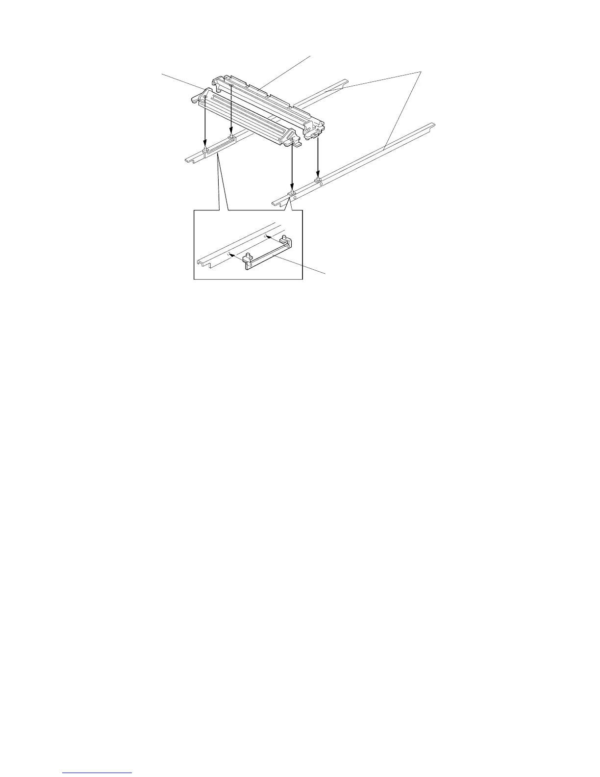
3. Set the scanner adjustment tools [A] on both guide rails [B] as shown.
NOTE: Scanner adjustment tools are available as a service part.
P/N: A1539001 (See the parts catalog.)
4. Manually set the 1st [C] and 2nd [D] scanner on the pins of the scanner
positioning bracket as shown.
5. Tighten the belt clamps.
NOTE: To remove the scanner positioning brackets, gently lift up both
scanner units and move them towards the home position.
6. Reassemble the machine and check the copy quality.
[B]
[D]
[C]
• Platen cover or DF
• Left scale
• Exposure glass
• Top cover
• Rear scale
• Rear cover
• Scanner HP. sensor
FSM 5-9 FT5535/4527/4522
 Loading...