Do you have a question about the Ricoh M290-27 and is the answer not in the manual?
Explains safety symbols and notations used in the manual for hazardous situations.
Provides fundamental safety guidelines for machine operation and manual reference.
Details symbols for power states like ON, OFF, and Standby for safe operation.
Specifies that only trained engineers with completed service training should perform replacements.
Mandates use of service manuals and approved parts for all maintenance procedures.
Crucial safety advice for personnel moving or working around the machine.
Safety checks required after installation, replacement, or adjustment procedures.
Lists essential tools required for machine maintenance and adjustments.
General safety guidelines to follow before and during maintenance procedures.
Safe usage and handling of organic cleaning agents during maintenance.
Critical safety measures for power connections, plugs, and cords to prevent hazards.
Guidelines for environmentally sound disposal of used toner, cartridges, and other parts.
Key points to instruct the user on machine operation and safety after service.
First aid and immediate actions for accidental toner contact with skin, eyes, or ingestion.
Information on toner flammability, safe storage locations, and handling procedures.
Steps to prevent personal harm, such as avoiding hot surfaces and moving parts.
Requirements for ozone filters and basic health advice regarding toner exposure.
Requirements for installation and maintenance personnel by customer service representatives.
Guidelines for disposing of replaced parts, batteries, and consumables.
Prohibits field repair of laser-based optical units; only subsystems are replaceable.
Confirms machine compliance with Chinese RoHS and absence of restricted materials.
Warning about hazardous laser radiation exposure and eye damage potential.
Explanation of common icons and abbreviations used throughout the manual.
Defines Short Edge Feed (SEF) and Long Edge Feed (LEF) for paper direction.
Explains symbols used for key presses and menu item selection.
Lists registered trademarks of various companies for identification purposes.
Directs users to the user guide for detailed machine specifications.
Guides users to the relevant manuals for driver and Virtual Operation Panel system requirements.
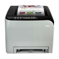
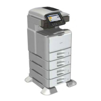
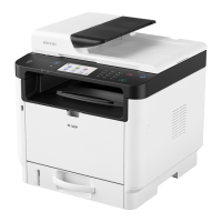
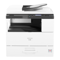
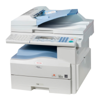
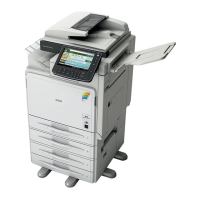
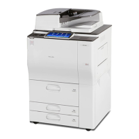
Compares SFP and MFP models, detailing their host interfaces and capabilities.
Highlights key features like drivers and operation panels for SFP and MFP variants.
Explains the messages displayed for Toner Near End, Toner End, and Waste Toner Full.
Important reminders for using the Virtual Operation Panel, CE Tools, and AIO cartridge.
Information on setting up the machine's general configuration, referring to the user guide.
Illustrates the paper's journey through the machine and lists key components.
Diagram showing the arrangement of internal drive components like motors and clutches.
Refers to the user guide for detailed installation requirements and procedures.
Refers to the user guide for instructions on how to maintain the machine.
Safety and preparation steps before starting any replacement or adjustment procedure.
Lists specific tools like hex screwdrivers and pliers needed for machine disassembly.
Instructions on how to print the machine's configuration page by pressing the power button.
Step-by-step instructions for removing the All-In-One (AIO) cartridge.
Detailed instructions for accessing and removing the machine's bottom cover.
Procedure for removing the top cover and associated parts on SFP models.
Notes that MFP models do not have a top cover, directing to scanner unit removal.
Instructions for removing the laser unit and adjusting registration values.
Checks and adjustments required after the laser unit has been replaced.
Step-by-step guide for removing and replacing the paper feed roller.
Instructions for removing and replacing the friction pad unit.
Steps to remove the registration roller by unlocking its bushing.
Steps to remove the image transfer roller and its associated parts.
Steps for removing the paper feed clutch and related gear.
Steps for removing the bottom plate lift clutch.
Detailed steps for removing the main motor, gears, and brackets.
Instructions for removing and replacing the machine's fan, noting decal orientation.
Step-by-step guide for removing the fusing unit and disconnecting its harness.
Procedures for removing and replacing the main board on SFP models.
Procedures for removing and replacing the main board on MFP models.
Steps to remove and replace the Wi-Fi printed circuit board.
Steps to remove and replace the Power Supply Unit (PSU).
Instructions for removing and replacing the High Voltage Power Supply (HVP).
Detailed steps for removing the scanner unit and its associated parts.
Procedure to replace the scanner open/close switch component.
Steps to remove the registration sensor from the machine.
Steps to remove the exit sensor from the machine.
Instructions for removing the thermistor component.
Steps to remove the bottom plate position sensor.
Steps to remove the paper size sensor.
Final steps for removing the paper size sensor from the feed guide bracket.
Guide to using the CE Tools software for machine adjustments and settings.
Details on adjusting leading edge and side-to-side registration for print quality.
Guide to setting fusing temperature based on paper type and operating modes.
Covers settings like magnification, density, PNP ID, and destination code.
How to view the current status of various machine components via CE Tools.
Steps for running output checks on components like motors and heaters.
General guidance for responding to service calls and diagnosing issues.
How to understand error messages, SC codes, and LED indicators on the status screen.
Basic advice like power cycling and checking connections for common errors.
Explanation of critical fusing errors and associated fire hazards requiring special handling.
Steps required to reset errors via CE Tools after resolving the underlying problem.
Defines severity levels (A, B, C, D) for SC codes and general reset procedures.
Details specific polygon motor timeout and lock signal errors with causes and solutions.
Explains bias leak occurrences, PWM signal abnormalities, and troubleshooting steps.
Details main motor lock signal detection errors and related causes.
Details errors related to the bottom plate position sensor and lift clutch.
Details errors related to the fusing unit failing to reach operating temperature.
Covers software-related high temperature errors in the fusing unit.
Covers hardware-related high temperature errors detected by the CPU port.
Details errors with the fuser lamp heating element remaining at full power.
Details errors detected by the motor thermistor at specific temperature thresholds.
Covers repeated paper jam errors in the fusing unit and automatic shutdown.
Details communication issues between the main board and other components.
Details scanner calibration failures and motor errors.
Explains how roller circumferences can cause image defects at regular intervals.
Addresses dark lines in halftone areas caused by low humidity, with a CE Tools solution.
Describes the various power saving modes (Stand-by, Engine Sleep, Deep Sleep) and transitions.
| Brand | Ricoh |
|---|---|
| Model | M290-27 |
| Category | All in One Printer |
| Language | English |