6
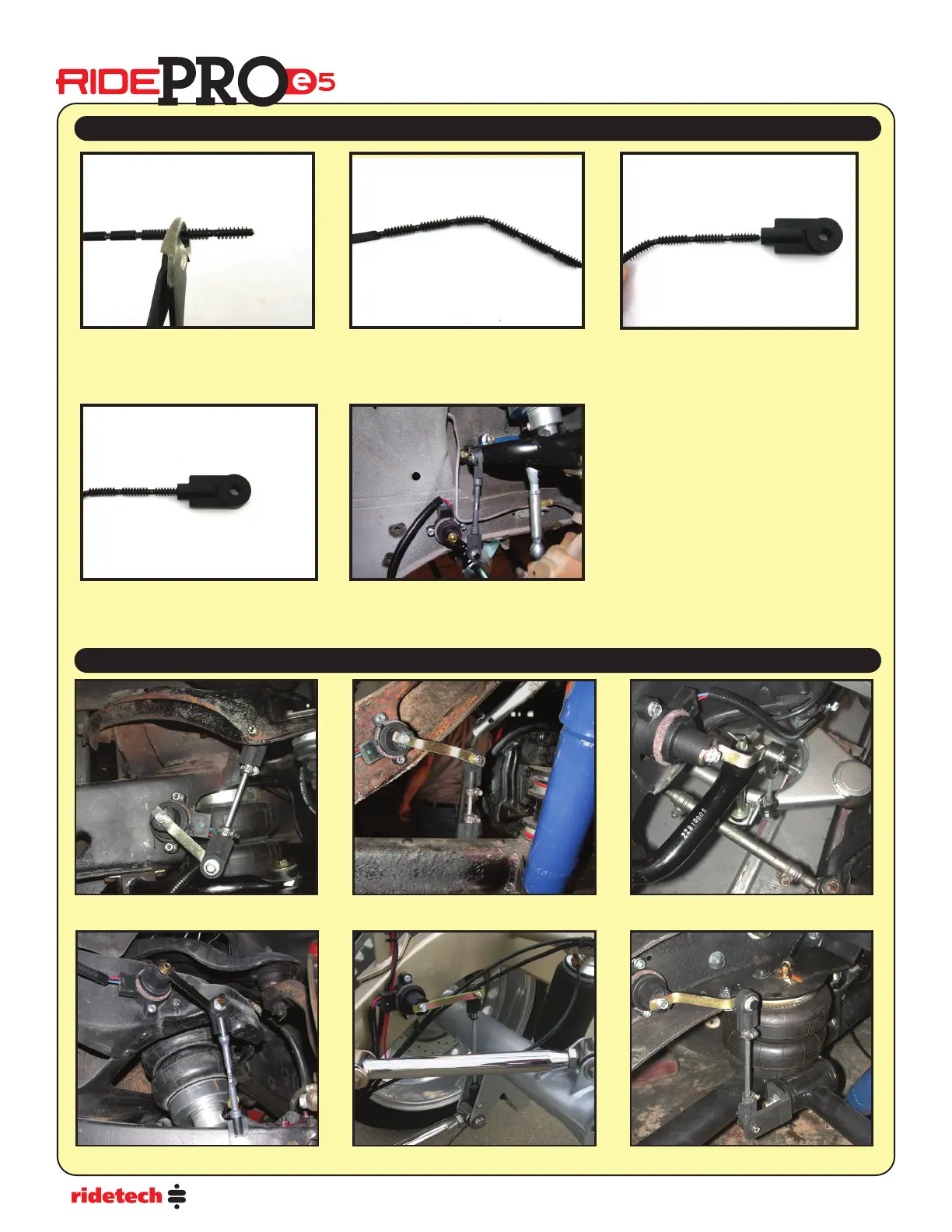
1- The linkage rod can be cut to length
using side cuts.
2- The linkage rod can be bent by hand.
This can come in useful when trying
to get clearance on an obstacle.
3- After getting the linkage cut to length
and shaped, line up the end with the
end link.
4- Push the end of the linkage into the
end link. The linkage doesn’t require
anything to hold it into the end link.
5
-
Once both sides of the linkage have
been nished, secure the linkage to
the sensor and suspension.
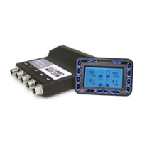
69 Camaro Front 58-64 Impala Front
Triangulated 4-Link Rear
Rear Trailing Arm
C-10 Truck Rear
Ride Height Sensors
Assembly of the Sensor Link Rods
Sensor Mounting Examples
55-57 Chevy Front