EasyManua.ls Logo

RIDGID 300 Series - User Manual

RIDGID 300 Series
3 pages
Print Icon
To Next Page IconTo Next Page
Loading...
5
418 Oiler
1 Gallon Nu-Clear Thread Cutting Oil
32 Transporter
Machine Assembly
WARNING
To prevent serious injury, proper assembly of the
Power Drive is required. Failure to mount the
Power Drive to a stable stand or bench may result
in tipping and serious injury. The following proce-
dures should be followed:
Mounting on No. 1206 Stand
1. Set up the 1206 Stand by opening legs and pushing
down on the tray. Legs should be stiff and the stand
should not wobble.
NOTE! The tristand leg stiffness can be increased or
decreased by the following procedure:
Place stand upside down on a flat surface.
Unlock tray so legs are loose.
Locate the set screw on the tray leg support on the
rear leg
(Figure 3).
Loosen the set screw to make the adjustment. To
increase stiffness, move the tray leg support up
towards the base. To decrease stiffness, move
the tray leg down towards the feet.
Tighten the set screw (increasing leg stiffness
increases tray tension).
2. Mount power drive on the stand using bolts and wing
nuts
(Figure 3).
Figure 3 – 300 Power Drive Mounted on No. 1206 Stand
with 418 Oiler
Mounting 311A Carriage and Tools
1. Inspect the support bars to insure they are forward
and secured by two (2) retaining ring assemblies.
Retaining ring set screws must be tight
(Figure 4).
300 Power Drive
Spindle Weight
Catalog Model Speed
No. No. Description RPM Lb. Kg.
41855 300 Only 115V,25-60 Hz 38 94 43.0
75075 300 Only 115V,25-60 Hz 57 94 43.0
41860 300 Only 230V,25-60 Hz 38 94 43.0
75435 300 Only 230V,25-60 Hz 38 94 43.0
15682 300 115V,25-60 Hz 38 212 96.2
Complete 1/2 – 2 NPT
15722 300 115V,25-60 Hz 57 212 96.2
Complete 1/2 – 2 NPT
REV/OFF/FOR
Switch
Chuck Jaw
Handwheel
Set Screw (2)
Retaining
Ring Assy. (2)
No. 1206
Stand
Foot Switch
Wing Nut (4)
Bolt (4)
Pipe
Centering
Device
Rear Leg
Set Screw
Question and Answer IconNeed help?

Do you have a question about the RIDGID 300 Series and is the answer not in the manual?

Summary

Machine Assembly

Mounting on No. 1206 Stand

Instructions for mounting the power drive on a specific stand, including leg stiffness adjustment.

Mounting 311 A Carriage and Tools

Procedures for attaching the carriage and associated tools to the power drive.

Machine Inspection

Machine and Work Area Set-Up

Overview

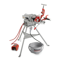
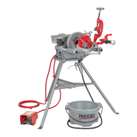
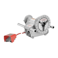
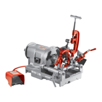
The RIDGID 300 Power Drive is a robust and versatile machine designed for threading, cutting, and reaming pipes, making it an essential tool for plumbers, pipefitters, and construction professionals. Its primary function is to provide the rotational power necessary to operate various pipe working tools, ensuring efficient and precise results.

Function Description

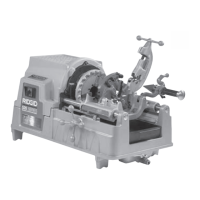
At its core, the 300 Power Drive serves as a motorized power source for pipe fabrication. It features a powerful motor that drives a speed chuck, which securely grips the workpiece. The machine is designed to be used with a range of accessories, including die heads for threading, cutters for precise pipe severing, and reamers for deburring and smoothing the inside of cut pipes. The directional switch allows the operator to select forward (FOR) or reverse (REV) rotation, accommodating different operations and tool requirements. A foot switch provides convenient and safe control over the machine's operation, allowing the operator to start and stop rotation while keeping their hands free to manage the workpiece and tools. The machine's design emphasizes stability and ease of use, particularly when mounted on a dedicated stand like the No. 1206, which enhances its portability and ergonomic setup.

Usage Features

The 300 Power Drive is engineered for practical and safe operation in various work environments.

  • Mounting and Stability: The machine can be securely mounted on a No. 1206 Stand, which features adjustable legs for stiffness and stability. This ensures the Power Drive remains steady during operation, preventing tipping and enhancing safety. The stand's design allows for easy setup and breakdown, making the machine portable.
  • Tool Integration: The Power Drive seamlessly integrates with a variety of RIDGID tools, including the 311A Carriage, 360 Cutter, 341 Reamer, and various die heads. The carriage assembly provides a stable platform for these tools, allowing them to be precisely positioned and advanced onto the workpiece. The quick-opening or self-opening die heads facilitate efficient threading by automatically disengaging when the thread is complete.
  • Workpiece Management: The speed chuck jaws are designed to securely grip pipes, preventing slippage during high-torque operations. For plastic or coated workpieces, special jaw inserts are available to prevent damage. When working with longer pipes, the use of pipe stands is recommended to prevent tipping and oscillation, ensuring a stable and safe work environment.
  • Control and Safety: The foot switch is a critical safety and operational feature, allowing the operator to maintain control over the machine's rotation without diverting their hands from the workpiece or tools. The directional switch (FOR/OFF/REV) provides clear selection of operation mode. The machine's setup guidelines emphasize creating a "safety zone" around the Power Drive and workpiece to prevent accidental contact with rotating parts.
  • Oiling System: The integrated 418 Oiler, often positioned beneath the Power Drive, supplies thread cutting oil to the workpiece during threading. This continuous lubrication and cooling are crucial for producing high-quality threads, extending die life, and preventing overheating. The oiler's chip tray collects metal shavings, keeping the work area cleaner.

Maintenance Features

Regular maintenance is crucial for ensuring the longevity, performance, and safety of the 300 Power Drive. The manual outlines a series of daily inspection procedures.

  • Pre-Operation Checks: Before each use, operators are instructed to ensure the Power Drive is unplugged and the directional switch is in the OFF position. This prevents accidental startup during setup or inspection.
  • Chuck Jaw and Insert Inspection: The speed chuck jaws should be cleaned with a wire brush, and the jaw inserts inspected for excessive wear. Worn inserts can compromise grip and lead to unsafe operation or damaged workpieces.
  • Cord and Plug Integrity: The power cord and plug must be inspected for any damage, modifications, or missing grounding pins. A damaged cord or plug poses a significant electrical shock hazard and must be replaced before use.
  • Component Integrity: Operators should visually inspect the Power Drive for any broken, missing, misaligned, or binding parts. Any unusual conditions, such as odd noises or excessive vibration, should be addressed by a qualified service technician.
  • Lubrication: The Power Drive spindle bearings require periodic lubrication according to the maintenance instructions to ensure smooth operation and prevent premature wear.
  • Tool Condition: Cutting tools and dies must be inspected for sharpness and damage. Dull or damaged tools can lead to poor thread quality, binding, and tool breakage. Replacing them as needed is essential for optimal performance.
  • Oiler Maintenance: The 418 Oiler's chip tray should be cleaned regularly to remove metal shavings and debris. The level and quality of the thread cutting oil must be checked, and the oil replaced or topped up as necessary. Using clean, high-quality thread cutting oil is vital for effective lubrication and cooling during threading.
  • Work Area Cleanliness: Maintaining a clean work area, free of oil spills, grease, and debris, is emphasized to prevent slips, falls, and other accidents. Clean handles and controls also ensure a secure grip, reducing the risk of injury.

By adhering to these usage and maintenance guidelines, operators can ensure the RIDGID 300 Power Drive continues to deliver reliable performance and maintain a high standard of safety in all pipe working applications.

RIDGID 300 Series Specifications

General IconGeneral
Horsepower Rating1/2 HP
Bolt Capacity1/4 in. to 2 in. (6 mm to 50 mm)
Motor1/2 HP, Universal Motor
Spindle Speed38 RPM
Rear Centering DeviceCam-action
Input Voltage115V
Speed RangeSingle Speed

Related product manuals