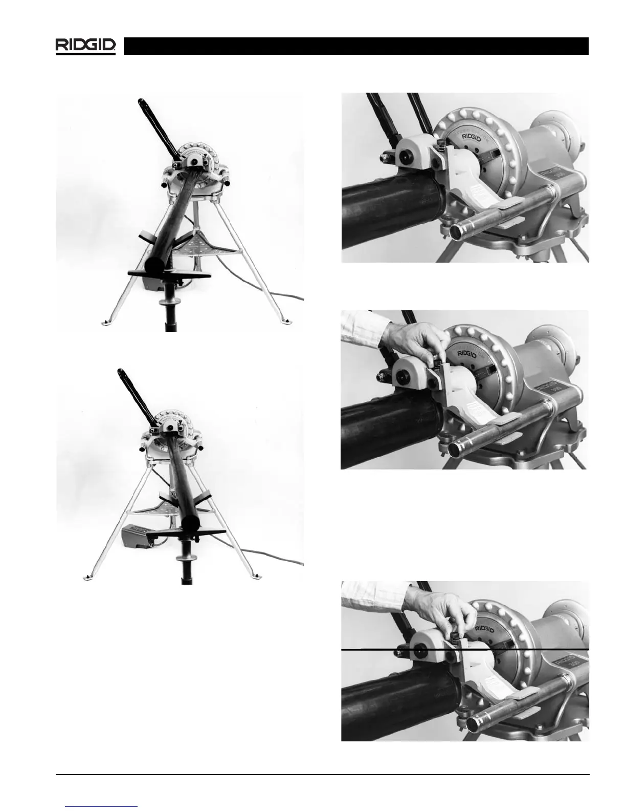
Figure 8A – Operating Machine in REVERSE (REV)
Position
Figure 8B – Operating Machine in FORWARD (FOR)
Position
Adjusting Roll Groove Depth
NOTE! To obtain the proper groove diameter, a test
groove should be performed when setting up or
changing pipe sizes.
1. Lift feed handle upward.
(Figure 9)
Figure 9 – Feed Handle in UP Position
2. Fully loosen depth adjustment screw.
(Figure 10)
Figure 10 – Loosen Depth Adjustment Screw
3. Tighten down depth adjustment screw the number of
turns indicated in
Chart B. (Figure 11)
NOTE!
Chart B
indicates adjustment needed when using
the 916’s standard roll set. See
Chart D
on
Page 12
for special note on 1
1
/
4
, 1
1
/
2
AWWA grooving and 1″
pipe grooving.
Chart C
is used when grooving
copper.
Figure 11 – Tighten Depth Adjustment Screw
916 Roll Groover
Ridge Tool Company 9