2. Push pivot pin back until stops.
3. Loosen depth adjustment screw.
4. Remove pivot pin.
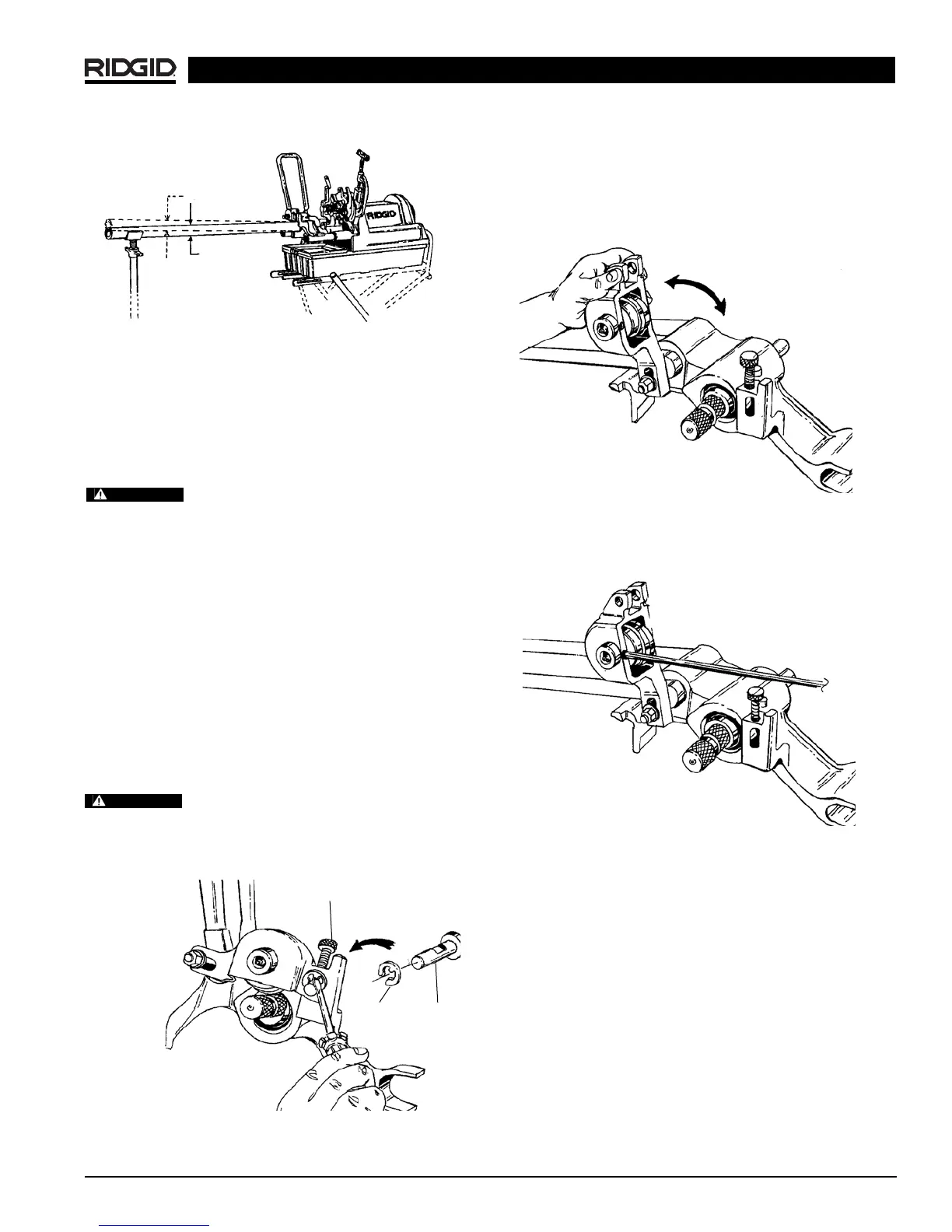
5. Raise up groove roll housing.
(Figure 15)
Figure 15 – Raise Up Roll Housing
6. Loosen set screw that holds groove roll shaft.
(Figure
16)
Figure 16 – Loosen Set Screw
7. Remove groove-roll shaft and groove roll.
8. Install proper groove roll in groove roll housing.
Section of the groove roll that forms the groove goes
towards the main housing.
9. When tightening set screw make sure it mates with
drill point in shaft.
10 Re-install roll housing by reversing steps 5-1.
Figure 13 – Adjusting Pipe to Same Angle as Machine
Grooving Short Lengths of Pipe
1. When running machine in forward direction, exert
pressure on pipe away from operator.
2. When running machine in reverse, exert pressure
on pipe toward operator.
Do not attempt to groove any pieces of
pipe shorter than 8″. Increases risk of fingers being crushed
in the grooving rolls. Do not reach inside pipe end.
Removing and Installing
Removing and Installing Groove Roll
NOTE! As groove dimensions are determined by the roll
set geometry, specific roll sets are required
when grooving the following:
2″ - 6″ Copper Tubing Types (K, L, M, DWV)
1″ Schedule 10 & 40
1
1
/
4
″ - 6″ Schedule 10 (1
1
/
4
″ - 3″ Schedule 40)
2″ - 3″ Schedule 40, 2″ - 6″ Schedule 10 AWWA
1
1
/
4
″ - 1
1
/
2
″ AWWA Schedule 10 & 40
Make sure power drive or threading
machine is unplugged from power source before chang-
ing the roll sets or removing the roll groover.
1. Remove E-Ring that holds pivot pin.
(Figure 14)
Figure 14 – Remove E-Ring
916 Roll Groover
Ridge Tool Company 11
2°
WARNING
WARNING
Depth Adj. Screw
Pivot Pin
E-Cup