Do you have a question about the RIDGID 975 and is the answer not in the manual?
Explains hazard symbols, rules for safe operation, and personal protection.
Covers proper tool handling, maintenance, and groover-specific safety.
Details product capabilities, technical data, and pre-use checks.
Guides work area prep and mounting for power-driven applications.
Guides work area prep and mounting for manual applications.
Step-by-step guide for grooving using a power source.
Adjusting for size and the actual grooving process.
Step-by-step guide for grooving manually.
Covers lubrication, cleaning, and parts replacement.
Information on repair, compatible items, and tool storage.
Solutions for common operational issues and pipe grooving problems.
Details on product warranty coverage and claims.
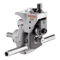
The RIDGID 975 Combo Roll Groover is a portable tool designed for forming rolled grooves in various types of pipe. It can be used for occasional on-site work but is not intended for high-volume or production work in a pipe fabrication shop. The grooves formed by the 975 Combo Roll Groover are dimensionally within the specifications of AWWA C606-06.
The 975 Combo Roll Groover mechanically advances a grooving roll into the pipe, which is supported by a drive roll, to form a rolled groove. The only adjustment necessary for operation is the depth of the groove. It is specifically designed for use either in-place or with a RIDGID Model 300 Power Drive (38 and 57 RPM Models). With the appropriate adapter (Catalog #67662), the unit can also work with the RIDGID Model 300 Compact Threading Machine. The tool includes a patented groove depth gauge to aid in setup and patented features to improve tracking during use.
The 975 Combo Roll Groover is versatile, allowing for both power-driven and in-place applications. When used with a power drive/threading machine, it's crucial to ensure the machine has a foot switch for safety and control. The power drive/threading machine should operate at a rotational speed of 57 rpm or less to reduce injury risk. For in-place applications, the groover should only be driven manually; powered devices like drills or impact tools should not be used as they can damage the groove and increase injury risk.
Before grooving, pipe must be cut to proper length, with ends cut square and free of burrs. Internal/external weld beads, flash, or seams must be ground flush at least 2" back from the end. Scale, dirt, rust, and other contaminants should be removed from the pipe ends to prevent clogging of drive knurls and ensure proper tracking. Using roll sets dedicated for stainless steel is recommended when grooving stainless steel to prevent ferrous contamination.
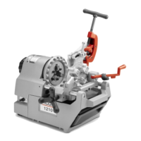
For the RIDGID 300 Power Drive, remove any carriage or attachments and ensure support arms are fully forward. Place the groover's support arms onto the power drive's support arms and secure the groover driveshaft in the chuck, tightening it with forceful counter-clockwise spins of the hammerwheel. For the RIDGID 300 Compact Threading Machine, an adapter kit (Catalog #67662) is required. Install the drive bar adapter onto the groover driveshaft, aligning set screws with flats, and firmly tighten. Position the threading machine carriage close to the chuck, moving the cutter, reamer, and die head out of the way. Place the adapter bracket over the rails of the 300 Compact and lock it with the pin. Secure the groover's support arms onto the adapter bracket's arms and tighten the threading machine chuck onto the drive bar adapter.
Position the foot switch for easy control of the power drive/threading machine, roll groover, and pipe. The operator should stand facing the roll groover, with access to the FOR/OFF/REV switch. Ensure a clear, level, stable, and dry work area with adequate lighting, free of flammable liquids or vapors. The power cord should follow a clear path to a properly grounded outlet.
A test groove should always be performed before the first groove of the day or when changing pipe size, schedule, or material. The integral groove depth gauge is used for pipe. Adjust the groove depth gauge so the correct step is under the adjusting screw head, then turn the gauge to the grooving position. For copper tubing, the integral gauge is not used; instead, the adjusting screw is backed off a specific number of turns from the top plate based on pipe diameter and type (refer to Chart B). After forming a test groove, measure the groove diameter with a diameter tape and compare it to specifications (Table I or III). Adjust the adjusting screw clockwise to increase diameter or counter-clockwise to decrease diameter (each ¼ turn changes diameter by approximately 0.02").
Move the FOR/OFF/REV switch to the REV (reverse) position; operating in FORWARD can cause the pipe to spiral out. Place one hand on the ratchet/feedscrew head and the other on the end of the ratchet. Press the foot switch to start the power drive. Monitor pipe rotation to ensure it stays in contact with the cover plate. Tighten the feedscrew ¼ turn per pipe rotation until the adjusting screw head stops against the top of the roll groover. Allow at least two more full rotations for uniform groove depth.
Ensure the pipe is solidly mounted and can withstand the groover's weight and grooving forces. There must be a minimum of 6½" clear space around the pipe and 2½" pipe extending past any obstruction. Install the ratchet and extension into the feedscrew and manual drive square. Place the driveshaft into the pipe, ensuring the cover plate is tight to the pipe end. Tighten the feedscrew until hand tight, then an additional ¼ turn with the ratchet.
To prevent pipe "spiraling" or "walking off" the driveshaft, ensure all instructions are followed. If tracking issues persist, slightly increase the pipe offset towards the operator (from ½ degree to 1 degree). The operator may need to apply slight force on shorter pipe sections while grooving, wearing leather gloves and cupping their hand around the middle of the pipe.
Before each use, inspect the roll groover for any problems. Ensure the power drive/threading machine is unplugged and the switch is in the OFF position. Clean any oil, grease, or dirt from the groover, handle, and ratchet. Check that support arms are tight, and that the groove roll and drive shaft turn freely. Inspect for broken, missing, or binding parts. Verify the warning label is present. Clean drive shaft knurls with a wire brush if dirty. Inspect groove roll and drive shaft for cracks, wear, or damage. Check ratchet and extension for smooth operation and secure locking. Lubricate as per instructions.
Lubricate the 975 Combo Roll Groover monthly with general-purpose grease. Grease fittings are located on the side of the operator's side of the base, the front of the slide block, and the end of the groove roll shaft. Add grease until a small amount is pushed out. Apply a light coat of grease to the feedscrew. The gearbox is greased for life and does not require additional grease unless opened.
Clean the driveshaft knurls with a wire brush daily or more often if needed.
When changing roll set parts, ensure drive and groove roll markings match to prevent improper grooves and leaks. Remove the roll groover from the power drive/threading machine and place it on a stable workbench.
Store the tool in a locked area, out of reach of children and untrained users, to prevent serious injury.
Most service needs are covered by the "Maintenance Instructions." Any problems not addressed should be handled by an authorized RIDGID service technician or returned to the factory. Only identical replacement parts should be used to maintain safety.