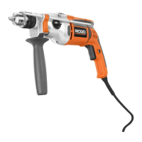
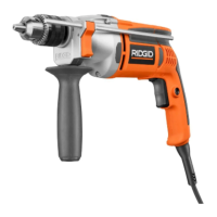
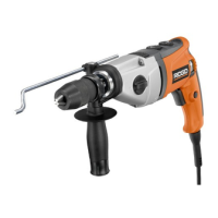
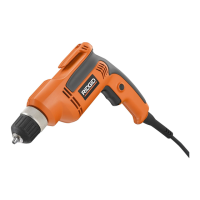
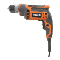
This document is an operator's manual for a RIDGID 1/2 inch Hammer Drill, model R5011, which is double insulated.
Function Description:
The RIDGID R5011 is a versatile power tool designed for both hammer drilling and normal drilling operations. It is engineered for dependability, ease of operation, and operator safety, promising years of rugged, trouble-free performance with proper care. The hammer drill is suitable for a variety of applications, including hammer drilling in concrete, brick, or other masonry, and normal drilling in wood, ceramics, plastics, fiberglass, laminates, and metals. It can also be used for mixing paint.
Important Technical Specifications:
- Chuck Capacity: 1/2 inch
- Input: 120 V, 60 Hz, AC only, 8.5 Amps
- Switch: VSR (Variable Speed Reversible)
- Hammer Speed: 0-19,000/0-57,000 BPM (Blows Per Minute)
- No Load Speed: Low (0-1,000 r/min. (RPM)) & High (0-3,000 r/min. (RPM))
- Net Weight: 6 lbs.
- Double Insulation: The tool features double insulation, eliminating the need for a three-wire grounded power cord. All exposed metal parts are isolated from internal motor components with protective insulation, reducing the risk of electric shock.
- Electrical Connection: Requires a 120 volts, 60 Hz, AC only power supply. Operating on direct current (DC) or with substantial voltage drops can lead to power loss and motor overheating.
- Extension Cord Usage: The manual provides a chart for recommended extension cord wire sizes (A.W.G.) based on cord length and ampere rating to prevent power loss and overheating. For outdoor use, an extension cord designated "WA" on its jacket is recommended.
Usage Features:
- Two-Speed Gear Train (HI-LO): The drill is equipped with a two-speed gear train, allowing selection between LO (1) for high torque and power applications, and HI (2) for faster operation during low torque applications. A slide switch on the side of the drill controls this selection.
- Drilling/Hammer Mode Selector: A selector on top of the motor housing allows switching between hammer mode (for hard materials like brick, tile, concrete with carbide-tipped bits) and normal drilling mode (for soft materials with twist drills, hole saws, etc.). The hammer drill is not designed for reverse hammering.
- Variable Speed Switch Trigger: The switch trigger provides variable speed control, with higher speed achieved by increased trigger pressure and lower speed by decreased pressure.
- Direction of Rotation Selector (Forward/Reverse): A selector located above the switch trigger allows changing the direction of bit rotation. For forward drilling, the selector is positioned to the left; for reverse, to the right. It is crucial to allow the chuck to come to a complete stop before changing the direction of rotation to prevent gear damage.
- Lock-On Button: This feature allows for continuous drilling during extended periods. To engage, depress the switch trigger, push and hold the lock-on button, then release the switch trigger. To disengage, depress and release the switch trigger.
- Auxiliary Handle Assembly: An auxiliary handle is provided for enhanced control and ease of operation. It can be rotated 360° and mounted on either side for left-hand use. The handle's tightness should be checked periodically.
- Depth Stop Rod: A depth stop rod is included to assist in controlling the depth of drilled holes. It is adjusted by depressing a button and positioning the rod relative to the drill bit.
- Chuck Key Storage: The chuck key can be conveniently stored in a designated holder when not in use.
- Anti-Vibration System: The hammer drill incorporates an anti-vibration system that absorbs impacts during drilling, allowing the body to flex to mitigate sharp impacts.
- Lighted Plug: The power cord features a lighted plug with a tool icon, making it easy to identify live tools.
- Clutch: The drill has a clutch mechanism that limits torque transfer to the user. Under excessive load, the clutch will slip and produce a ratcheting sound, disengaging the bit from the gear train to prevent tool damage or loss of control.
- Drilling Best Practices:
- For hard, smooth surfaces, use a center punch to mark the hole location.
- When drilling metals, use light oil on the drill bit to prevent overheating and prolong bit life.
- Avoid forcing the drill or applying side pressure to elongate holes; let the tool do the work.
- Be prepared for binding at bit breakthrough, as the drill may kick in the opposite direction.
- For large holes in metal, start with a small bit and finish with a larger one.
- When drilling through wood, place a block behind the workpiece to prevent splintering.
- For tile, practice on a scrap piece to determine optimal speed and pressure.
Maintenance Features:
- General Maintenance: Avoid using solvents for cleaning plastic parts, as they can cause damage. Use clean cloths to remove dirt, dust, oil, and grease.
- Lubrication: All bearings in the tool are pre-lubricated for the life of the unit under normal operating conditions, requiring no further lubrication.
- Chuck Removal and Retightening: The manual provides detailed instructions for removing and replacing the chuck, including loosening the chuck screw (which has left-hand threads) and using a hex key and mallet to loosen or tighten the chuck on the spindle.
- Service: Servicing requires extreme care and knowledge and should be performed by a qualified service technician, ideally at an authorized service center using only identical replacement parts. Unauthorized parts or improper maintenance can lead to shock or injury.
- Cord Inspection: Periodically inspect tool cords for damage and have them repaired by an authorized service center if necessary.
- Damaged Parts Check: Before further use, check for misalignment or binding of moving parts, breakage, and any other condition that might affect operation. Damaged parts should be repaired or replaced by an authorized service center.
Warranty:
The RIDGID R5011 comes with a 3-Year Limited Service Warranty, covering defects in workmanship or materials and normal wear items (brushes, chucks, motors, switches, cords, gears, and cordless batteries) for three years from the purchase date. A 90-Day Satisfaction Guarantee Policy allows for a full refund or exchange within the first 90 days if dissatisfied. The warranty requires proof of purchase and applies only to the original purchaser at retail. It does not cover misuse, abuse, neglect, alteration, modification, or repairs by unauthorized service centers. Consumable accessories like blades, bits, and sandpaper are not covered. Implied warranties are disclaimed to the extent permitted by law, or limited to three years where disclaimers are not allowed.