EasyManua.ls Logo

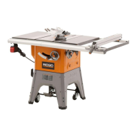
RIDGID TS 2400 User Manual

RIDGID TS 2400
68 pages
To Next Page IconTo Next Page
Page #1 background imageLoading...
Page #1 background image

Table of Contents

Questions and Answers:

RIDGID TS 2400 Specifications

General IconGeneral
TypeTable Saw
Blade Diameter10 inches
Motor Power15 Amps
Max Cut Depth at 90 Degrees3-1/8 inches
Max Cut Depth at 45 Degrees2-1/4 inches
Weight90 lbs
Arbor Size5/8 inches
Voltage120V
Dust Port Size2-1/2 inches
Max. RPM5, 000 RPM

Summary

Safety Instructions for Table Saw

Safety Signal Words

Explains DANGER, CAUTION, and WARNING terms used in the manual.

Before Using The Saw

Essential safety warnings and steps before the initial use of the saw.

Installing and Moving the Saw

Safety precautions and advice for installing and moving the table saw.

Pre-Use Inspections

Critical checks and inspections to perform before each use of the saw.

Preventing Jams, Slips, and Kickbacks

Detailed instructions to minimize the risk of jams, slips, and kickbacks.

Personal Protection

Safety guidelines for eyes, hands, face, and ears, including PPE.

Sawblade Spinning Safety

Crucial safety measures to follow when the sawblade is spinning.

Rip and Crosscut Specific Safety

Additional safety instructions tailored for rip and crosscut operations.

Glossary of Terms for Woodworking

Definitions

Definitions of key woodworking terms used in the manual.

Key Terms

Definitions for terms like Push Stick, Rip Cut, Thru-Sawing, and Workpiece.

Motor Specifications and Electrical Requirements

Power Supply and Motor Specifications

Details on the saw's motor and required power supply specifications.

General Electrical Connections

Safety guidelines and procedures for making electrical connections.

Wire Sizes

Guidance on selecting appropriate extension cord wire sizes for safety.

Getting to Know Your Table Saw

Component Identification

Diagram and labels identifying the main parts of the table saw.

Key Controls and Features

Explanation of controls like Rip Fence, On-Off Switch, and Blade Guard.

Blade Adjustment Mechanisms

How to operate the blade elevation and bevel adjustment controls.

Storage Features

Locations for storing accessories like the blade guard and wrenches.

Alignment and Adjustments

Tools Needed and Initial Checks

List of tools for alignment and initial checks like table insert.

Blade Parallelism and Squareness

Procedures to ensure blade parallelism and squareness to the table.

Rip Fence and Table Extension Alignment

Steps for aligning the rip fence and sliding table extension.

Sawblade Installation and Removal

Safe procedures for removing and installing the sawblade.

Miter Gauge Alignment

How to align the miter gauge stops and ensure smooth movement.

Mounting Your Saw

Workbench and Legset Mounting Procedures

Detailed steps for securely mounting the saw to a workbench or legset.

Alternative Mounting Methods

Instructions for alternative mounting using C-clamps or sawhorses.

Basic Saw Operations

Using the Miter Gauge

Guidance on using the miter gauge for various cuts like crosscutting.

Crosscutting Techniques

Procedures and safety for performing crosscuts and repetitive cuts.

Rip Cutting Techniques

Instructions and safety for performing rip cuts using the rip fence.

Specialized Cuts

How to perform specialized cuts like resawing, dadoing, rabbeting, and molding.

Maintenance and Troubleshooting

Routine Maintenance Procedures

Regular maintenance tasks including cleaning, sharpening, and lubrication.

Troubleshooting Common Issues

Identifying and resolving common problems like vibration and inaccurate cuts.

Motor Troubleshooting

Diagnosing and fixing issues related to the saw's motor.

Repair Parts

Parts Identification - Figure 1

Diagram and list of parts for the main table saw assembly.

Parts Identification - Figure 2

Diagram and list of parts for various components of the saw.

Parts Identification - Figure 3 (Miter Gauge)

Diagram and list of parts specifically for the miter gauge assembly.

Parts Identification - Figure 4 (Fence)

Diagram and list of parts for the fence assembly.

Parts Identification - Figure 5 (Guard)

Diagram and list of parts for the guard assembly.

Warranty Information

Satisfaction Guarantee and Limited Warranty

Details on the 90-day guarantee and three-year limited warranty.

Obtaining Service and Exclusions

Procedures for service, warranty limitations, and exclusions.

Related product manuals