20147064
16
Installation
5.9 Gas feeding
5.9.1 Gas feeding line
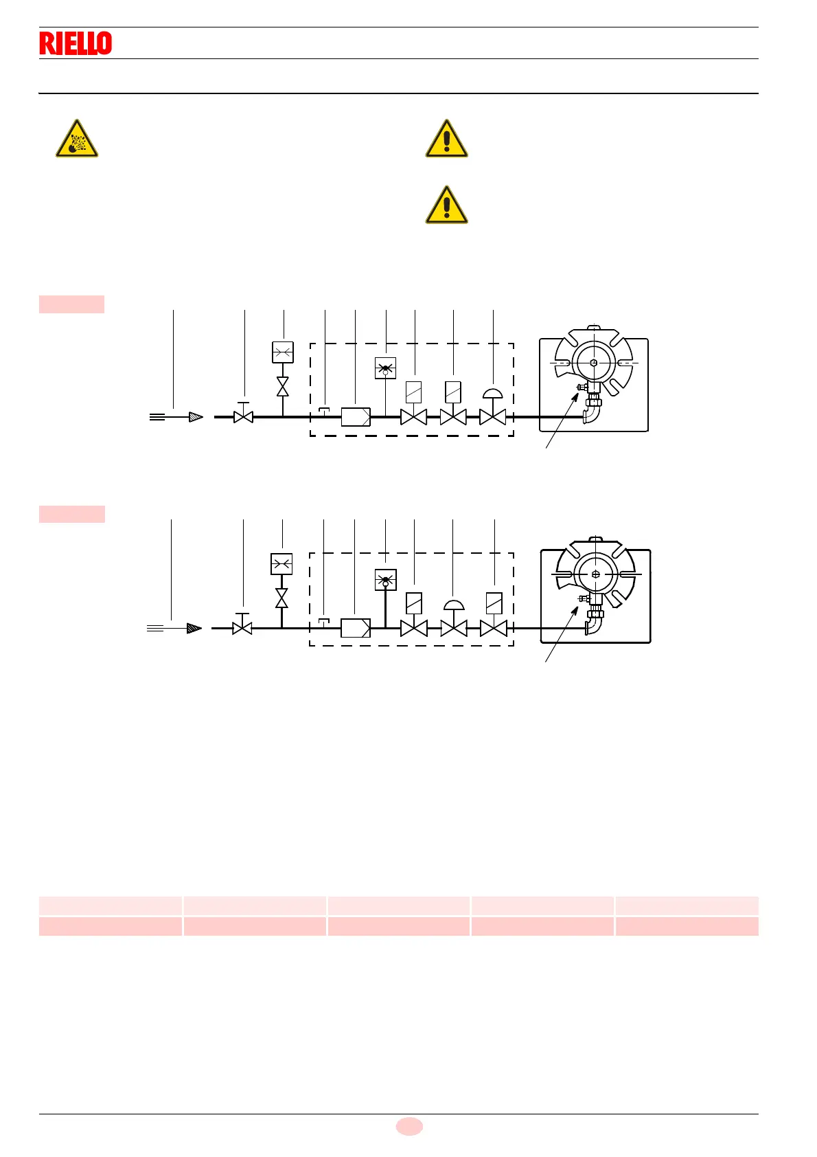
Key (Fig. 13 - Fig. 14)
1 Gas input pipe
2 Manual gate (the responsibility of the installer)
3 Gas pressure gauge (the responsibility of the installer)
4Filter
5 Gas pressure switch
6 Safety valve
7 Pressure stabiliser
8 Adjustment valve
M1 Gas-supply pressure test point on the pressure switch
M2 Pressure coupling test point
5.9.2 Gas train
Approved according to standard EN 676 and provided separately
from the burner. Supplied separately for its adjustment, see the
enclosed instructions.
The train-burner combination is indicated in Tab. E.
Tab. E
Explosion danger due to fuel leaks in the pres-
ence of a flammable source.
Precautions: avoid knocking, attrition, sparks and
heat.
Make sure the fuel interception tap is closed be-
fore performing any operation on the burner.
The fuel supply line must be installed by qualified
personnel, in compliance with current standards
and laws.
The heat output and gas pressure in the head
data refer to operating with the gas butterfly
valve fully open (90°).
Fig. 13
1
D7733
M2
2 3 M1 4 5 6 8 7
MBC 65/1
Fig. 14
D5069
M2
1 2 3 M1 4 5 6 7 8
MB 405/1
Code Model
Connections
Use
Gas train Burner
3970569 MBC 65/1 - RSD 20 Rp 1/2 Rp 1/2 Natural gas and LPG
3970530 MB 405/1 - RSD 20 Rp 1/2 Rp 1/2 Natural gas and LPG