17
20147064
Installation
5.9.3 Gas train installation
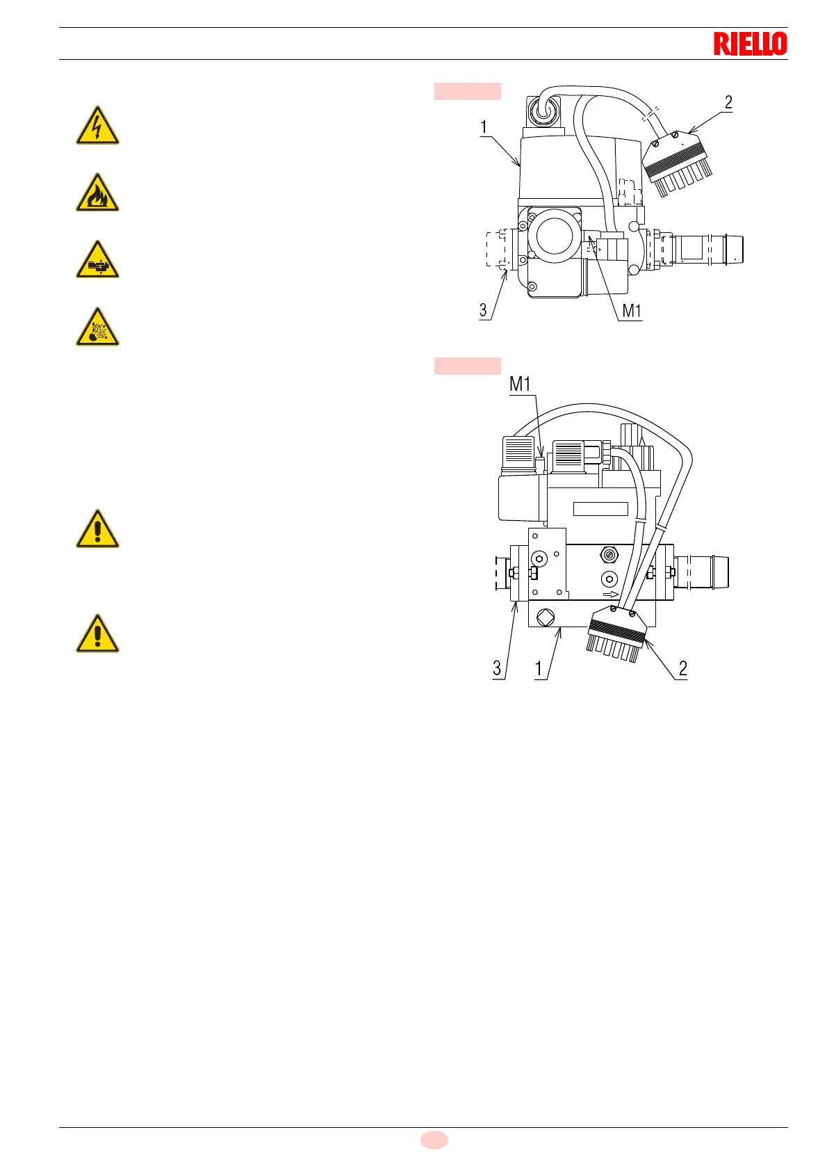
The gas train MBC 65/1 1)(Fig. 15) leaves the factory ready for
installation to the burner's left. If it is to be installed on the right,
fit the valve turned by 90° with respect to the gas-out flange and
with the gas pressure switch pointed upwards.
The gas train MBC 405/1 1)(Fig. 16) leaves the factory ready for
installation both on the right and left of the burner.
Connection between the gas supply line and the train must be
made using the gas-in flange 3) supplied, and fastening screws.
Connect the 6 pin plug 2)(Fig. 15 and Fig. 16) of the gas train to
the 6 pole socket 9)(Fig. 4 on page 10) of the burner.
Disconnect the electrical power using the main
switch.
Check that there are no gas leaks.
Pay attention when handling the train: danger of
crushing of limbs.
Make sure that the gas train is properly installed
by checking for any fuel leaks.
It is best to tighten screws in a criss-cross pattern.
Do not, under any circumstances, install the valve
with the coil facing down.
Once installation is complete, you must check for
fuel leaks and make sure the gas train is working
properly.
 Loading...


