20147064
20
Installation
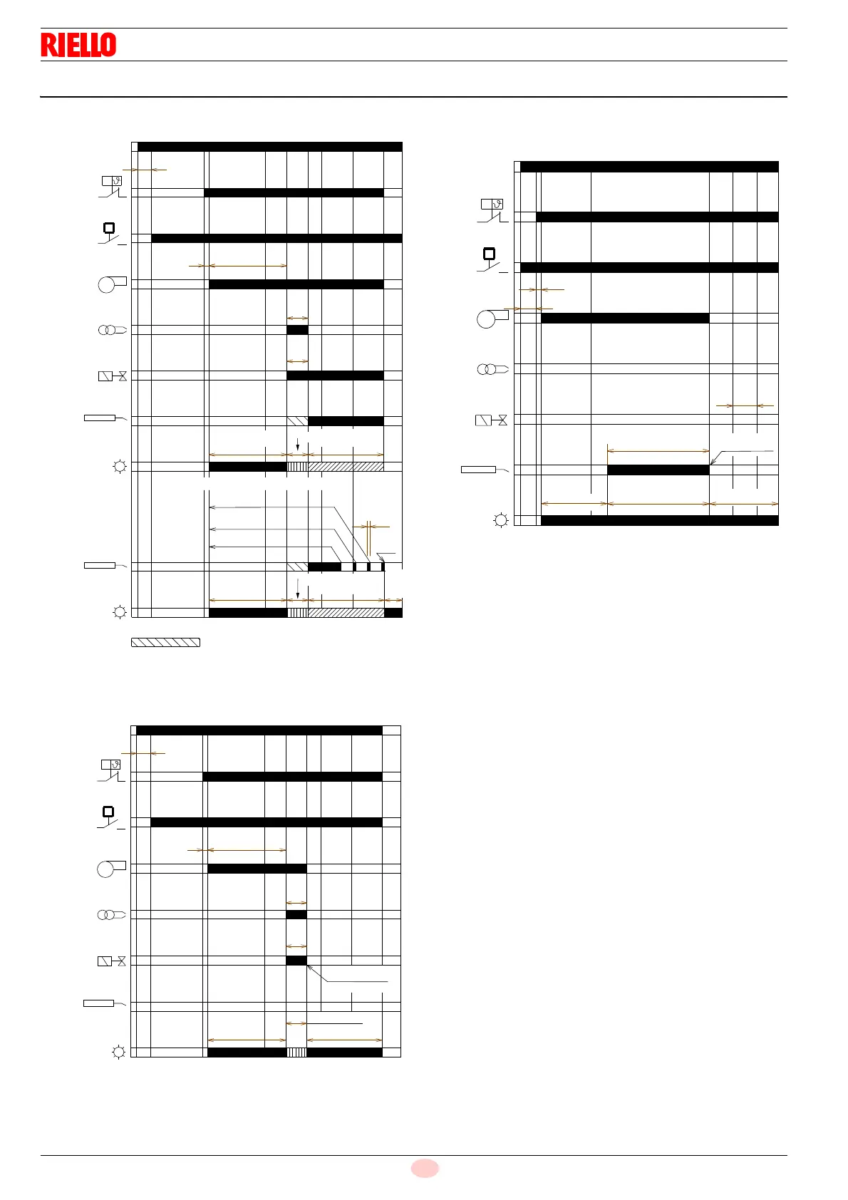
5.11 Operating programme
Key
FM –Fan motor
HT – Heat request
ID – Ignition device
LED – LED colour inside the button
PG – Low gas pressure switch
SO – Ionisation probe
t1 – Standby time
t2 – Initialisation time for checking
t3 – Pre-purging time
t3l – Checks for presence of extraneous light during pre-purg-
ing phase
t4i – Total ignition time
t4l – Reaction time to achieve safety lockout due to lack of fail-
ure
ts – Safety time
V1 – Gas valve
t
2
t
1
t
3
t
4i
t
s
HT
FM
ID
V1
LED
P
M
LED
t
4l
PG
P
SO
SO
POWER SUPPLY
Signal not requested
Orange
blink
Green blink
Lockout
No flame during operation
Green blink
Green
Fig. 19
Normal operation
20136055
Fast red
blink
Green
Orange
blink
t
2
t
1
t
3
t
4i
t
s
HT
FM
ID
V1
LED
P
M
PG
P
SO
Lockout
Green blink
Red
Lockout due to ignition failure
20136056
POWER SUPPLY
Fig. 20
Orange
blink
LED
t
2
t
1
HT
FM
ID
V1
P
M
t
3
l
PG
t
s
P
SO
Red, green blink
Lockout
Red
Lockout due to extraneous light during pre-purging
POWER SUPPLY
Fig. 21
20136057
Orange
blink