27
INSTALLATION
SERVICE DISPLAY
J6-1 b
J6-2 bl
LUE SENSOR
J6-5 b
J6-12 h
204
Enable /
Disable
TOUCH SCREEN
+
-
J6-8 h
J6-1 b
J9-1 b
J9-3 h
J9-2 b
J9-4 h
+
J6-11 h
J6-4 b
J6-13 h
J6-6 b
J6-14 h
J6-7 b
J8-2 h
J8-1 b
FLOWMETER
J7-6 b
J7-7 bl
J7-8 h
W. PRESSURE
FLUE
PR
ESSURE
SWITCH+
CONDENS.
PRESSURE
SWITCH
SWITCH
J6-8 h
RETURN T. SENSOR
J6-3 b
J6-10 h
203
WATER THERM.
SAFETY LIMIT
J12-1 b
J12-4 h
J12-5 h
J12-2 b
SUPPLY TEMP.
SENSOR
202
212
MIN+MAX GAS
PRESSURE
SWITCH
J7-9 b
J7-10 h
LWCO
AIR PRESSURE
J7-4 h
J7-3 h
J7-2 b
J7-2 b
J11-2 red
J7-5 b
J7-10 h
(ONLY AR 500)
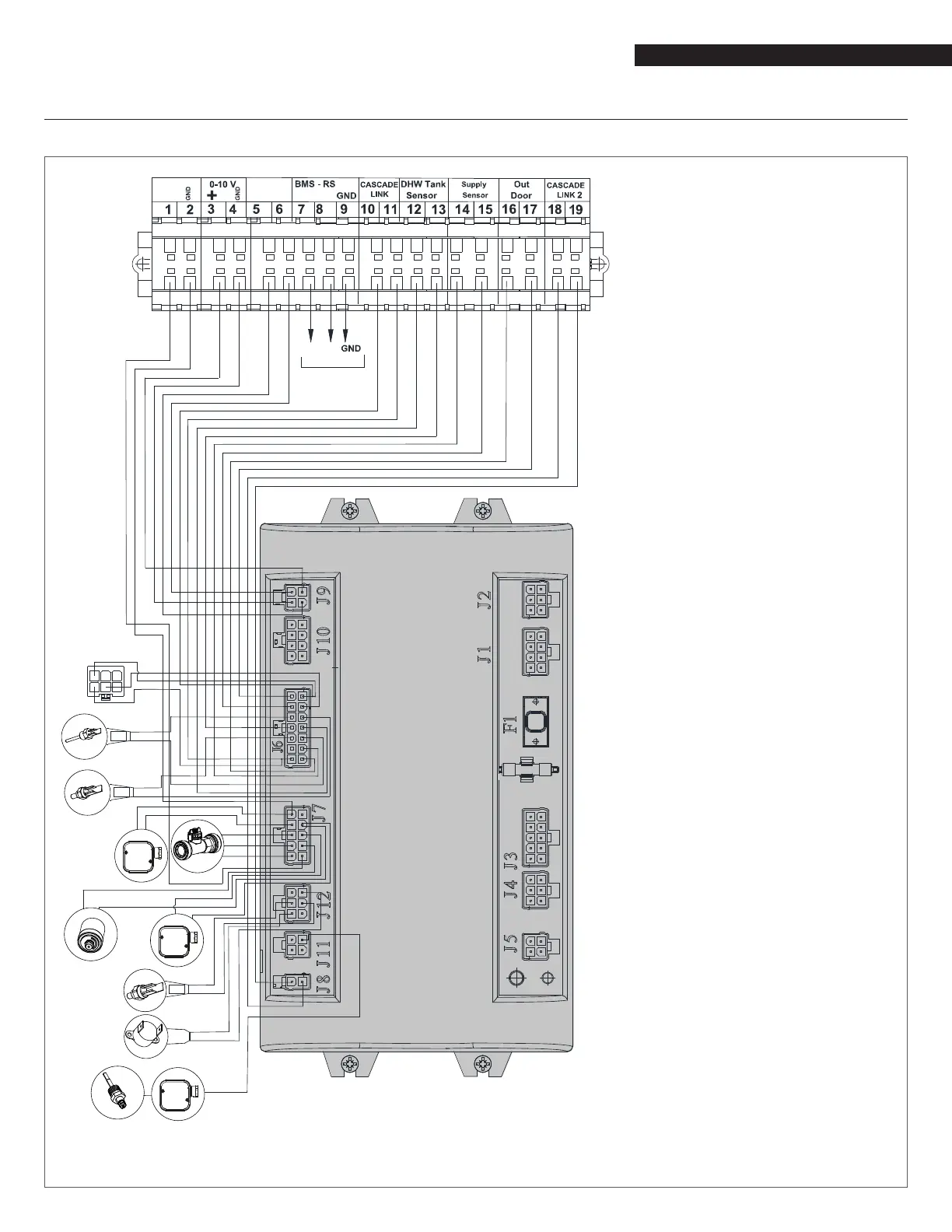
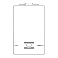
3.16 Wiring diagram
Key
EP Exhaust ue temperature
sensor
FP Supply temperature sensor
RP Return temperature sensor
ST Water high-limit safety
thermostat
MPS Low Water Cut Off
FS Flue gas air pressure switch
FL Flow-meter
DCC Display and control card
TB1 Low-voltage terminal
board
0-10V 0-10V input
RT Room/heat demand
thermostat
Modbus Modbus outlet
DHW Indirect storage tank
sensor (accessory)
SP System temperature sensor
(accessory)
OS Outdoor temperature
sensor (accessory)
LWCO Low Water Cut Off
Cable colour
b brown
h blue
r red
w white
bl black
g yellow/green
y yellow
gr green
gy grey