26
INSTALLATION
ENGLISH
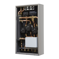
2.6 Electrical connections
The BAG
3
is pre
arranged with rubber cable feed-throughs (1) located
in the top section of the box allowing wiring to be passed through.
Below is an explanation of how to correctly connect the BAG
3
on
the boiler and on devices.
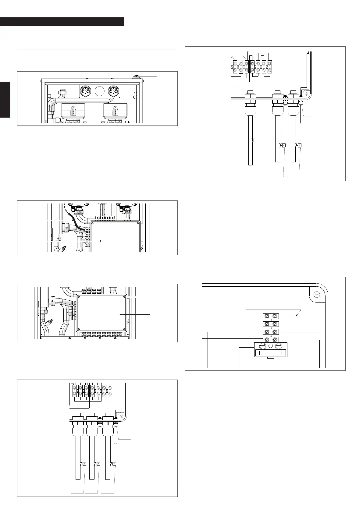
9
Before carrying out any electrical intervention, set the main
system switch to "off".
Connecting the BAG
3
to the electrical power supply
− Pass the cable (2) which comes out of the electrical con-
nection box (3) through the cable feed-through (1) and
connect it to the electrical power supply (phase-neutral-
earth) making sure not to connect it below the boiler fuse.
2
3
Access to the BAG
3
connection terminals
− To access the BAG
3
connection terminals, loosen the four
screws (4) and remove the cover (3).
3
4
Connecting the BAG
3
to the ambient thermostats/chrono-thermostats
− Carry out the connections of the ambient thermostats (TA)
and/or chrono-thermostats (CT) of each zone, as indicat-
ed in the diagram below. Before connection, eliminate
the relative jumper (TA1,TA2 or TAt3).
24
5
1
Cavo ingresso
di rete 230V
3
TA2 nero
TA1 rosso
nero
rosso
TA3 grigio
grigio
grigio
grigio
TA3 dopo aver
rimosso
ponticello
GRIGIO
TA1 dopo aver
rimosso
ponticello
ROSSO
TA2 dopo aver
rimosso
ponticello
NERO
BAG
3
2 MIX BASIC
9
24
5
1
Cavo ingresso
di rete 230V
3
blu
TA1 rosso
rosso
rosso
marrone
TA3 grigio
rosso
grigio
marrone
grigio
grigio
marrone
blu
rosso
rosso
blu
rosso
nero
TBT 1
TA3 dopo aver
rimosso
ponticello
GRIGIO
in morsettiera
TA1 dopo aver
rimosso
ponticello
ROSSO
in morsettiera
BAG
3
MIX BASIC
The ambient thermostats (TA) and/or chrono-thermostats
(CT) of the low and high temperature systems must be con-
nected directly to the BAG
3
using a cable with a minimum
section of 1 mm
2
.
9
The
load represented by the pump will weigh directly on the
corresponding ambient thermostat (TA) and/or chrono-ther-
mostat (CT), therefore the TA and/or CT contact must be adapt-
ed to the application and be compatible with the electrical
rate of the pump not less than 6A (230Vac-50Hz).
Connecting the BAG
3
to the boiler
− Connect the CONNECT LE to the boiler (GEN) as indicated in
the diagram below.
9
nero
nero
marrone
blu
marrone
Fusibile 3.15A F
g/v
blu
g/v
marrone
blu
INGRESSO RICHIESTA
CALORE
CALDAIA o GENERATORE
Connect the mammut (B-B) of the BAG
3
to the mammut (TA)
of the boiler using a cable with a minimum section of 2x0.5
mm
2
(please refer to the wiring diagram in the instruction
booklet for the installer of the specic boiler).
9
When using a phase-phase power supply, use a tester to
determine which of the two wires has the greater potential
compared to the earth and connect it to the L terminal. Con-
nect the remaining wire to the N terminal.
9
For oating power supplies, i.e. those which have no earth
connection, an insulation transformer must be used with a
secondary unit connected to the earth.
9
It is mandatory:
− to use a multi-pole trip-switch to disconnect the line in
compliance with CEI-EN standards (contact opening at
least 3 mm)
− to use cables with a 1.5 mm
2
section and respect the L
(phase) - N (neutral) connection
− that the amperage on the switch is adequate for the boil-