20015900
4
GB
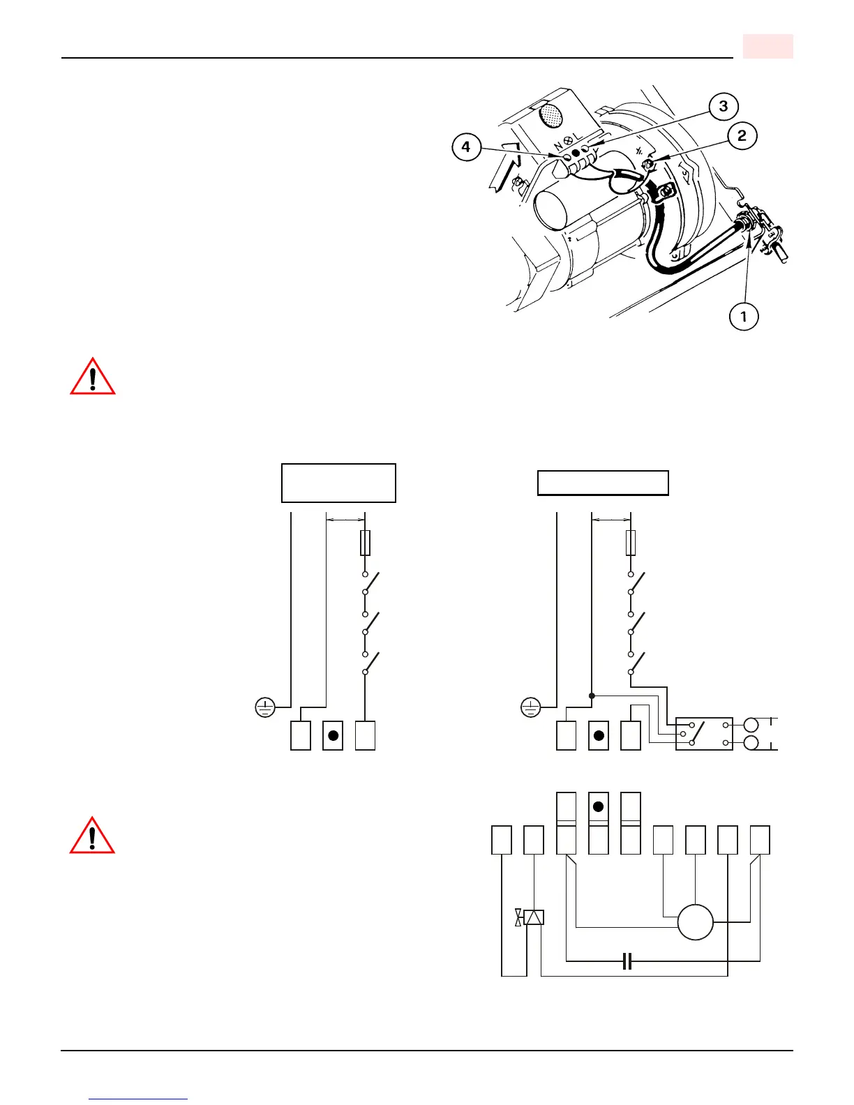
ELECTRICAL CONNECTIONS
It is advisable to leave the control box off the sub-base while
completing the electrical connections to the burner.
1) Electrical connector
2) Earth ground conductor terminal
The burner may be controlled using either a DIRECT LINE
VOLTAGE control circuit (120V AC 60 cycle) OR a LOW
VOLTAGE control (24V AC 60 cycle) using models Riello or
Honeywell R8038A 24v relays or a LOW VOLTAGE
THERMOSTAT INPUT (T-T).
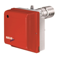
Following the wiring diagram on the next page, make electrical
connections to burner. All wiring must be done in accordance
with existing electrical codes, both National and Local.
Do not activate burner until proper oil line connections have been made, or failure of the pump shaft seal may
occur.
APPLICATION FIELD WIRING - RIELLO 530 SE/C PRIMARY CONTROL
REMOTE SENSING OF
SAFETY LOCKOUT
The SAFETY SWITCH in
the 530 SE/C CONTROL
BOX is equipped with a con-
tact allowing remote sens-
ing of burner lockout. The
electrical connection is
made at terminal 4 (
•
) on
the SUB-BASE.
Should lockout occur the
530 SE/C CONTROL BOX
will supply a power source
of 120Vac to the connection
terminal.
The maximum allowable
current draw on this termi-
nal (4) is 1 Amp.
If a neutral or
ground lead is
attached to this
terminal, the
CONTROL BOX on the
burner will be damaged
should lockout occur.
EARTH GROUND (Green)
NEUTRAL (White)
HOT LINE (Black)
EARTH GROUND (Green)
NEUTRAL (White)
HOT LINE (Black)
TRANSFORMER
Blue
White
Black
Brown
White
Blue
Brown
Black
CAPACITOR
VALVE
MOTOR
COIL
234567891
NL
NLN
L
FACTORY
WIRED
SUB-BASE
T
T
24V
AC
120V
AC
LINE SAFETY
SWITCH
OPERATING
LIMIT SWITCH
SAFETY
LIMIT SWITCH
FUSE 15A
120V
AC
Black
White
LINE SAFETY
SWITCH
OPERATING
LIMIT SWITCH
SAFETY
LIMIT SWITCH
FUSE 15A
SWITCHING RELAY
M
~
D5995
DIRECT LINE
LOW VOLTAGE
VOLTAGE