20015900
13
GB
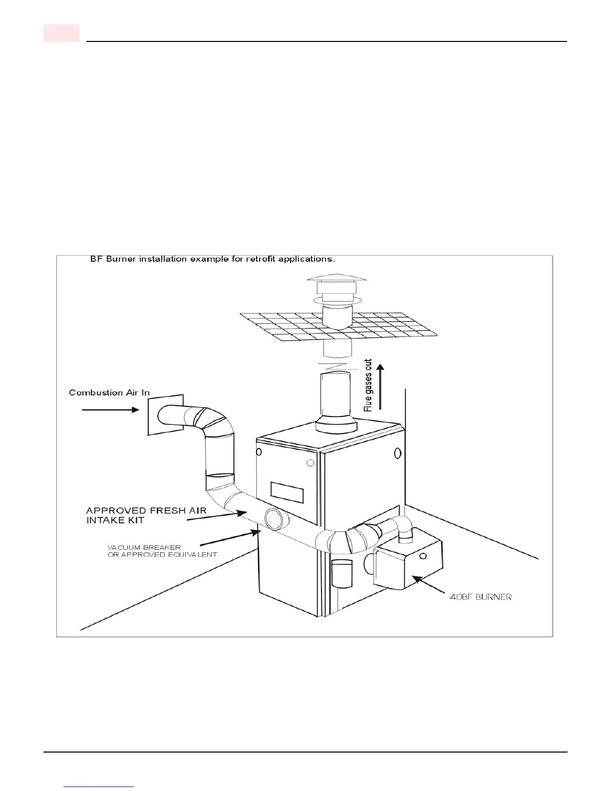
A TYPICAL LAYOUT FOR BF BURNER INTAKE AIR
A) Use an approved air intake kit.
B) Always keep intake air run to the minimum.
C) Maximum intake air run of 4 (inch) diameter, flexible or rigid type of venting = 100í
D) Reduce intake air length by 10’ for every 90° elbow used. 5’ for every 45° elbow used.
E) It is suggested that air intake venting be insulated with R7 (min) foil lined insulation a minimum of 10’ from air intake
source. (Prevent condensation or corrosion of intake air venting)
F) Used approved type of intake air vacuum breaker and to be installed in the same room and the burner, for the event
of intake air source being blocked, this device should be tested to prove that in the event of intake air source is blocked
that the vacuum breaker balancer is set correctly and can provide sufficient air for combustion for the burner. If the
room that the burner is installed into cannot provide enough air or air quality is a concern, an additional air inlet source
will have to be providing to this room.
THIS INTAKE AIR LAYOUT FOR CHIMNEY APPLICATIONS ONLY