3254
12
GB
ORIFICE INSTALLATION AND COMBUSTION HEAD SETTING
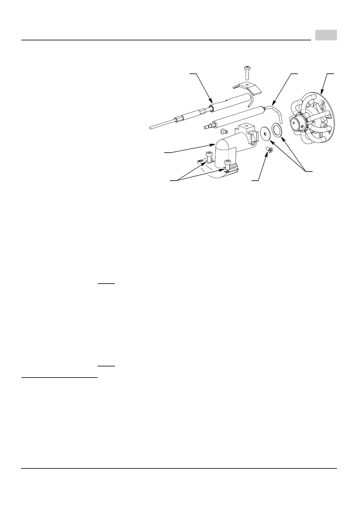
A proper orifice (C) has to be installed in
the combustion head gas line, according to
TABLE 1. A complete set of gas orifices is
delivered with the burner packaging as
equipment. The burner leaves the factory
with the A3 orifice already installed. In
case another orifice has to be installed, fol-
lowing the instructions below.
To remove the drawer assembly from the
manifold (B), follow the procedure below:
1) Disconnect 24v leads at the gas valve.
2) Separate the burner chassis from the
combustion head by removing the lock-
nut.
3) Loosen the two Allen screws (A) with-
out taking them out.
4) Withdraw the head, turning it 180
degrees.
5) Pull out head, leaning it towards the bottom.
6) Remove the ignition electrode (D) and the ionization probe (E).
7) Unscrew the screw (F) and remove the gas diffuser (G).
8) Install the proper orifice (C) and seal according to TABLE 1.
9)
Refit following the above procedure in the reverse order (verify the ignition electrode and the ionization probe
positions according to page 5).
Slide the elbow (B) so that the number on the indicator scale aligns with the back edge of the air tube.
See TABLE 1 for set points. Tighten the two Allen screws (A).
Example (for natural gas):
For a desired burner output of 114,500 Btu/hr, the orifice would be B3 and the combustion head setting would be 1.
All settings in TABLE 1 are obtained with zero (0) pressure in the combustion zone and at normal operating tem-
peratures. i.e.; steady state hot conditions.
Note: Burner must be fired ONLY
with fuel that is listed on the burner serial label.
MANIFOLD PRESSURES
Manifold gas pressure for various firing rates should be set by adjusting the gas regulator of the gas valve, (see
figure at page 6). To check manifold gas pressure, attach a manometer to the manifold test point, shown on typical
gas train layout. Approximate manifold pressure settings are indicated in TABLE 1.
Example (for natural gas):
For a burner to be fired at 114,500 Btu/hr, the manifold pressure would be approximately 3.5" wc.
In case of lower or higher manifold pressure, install an orifice with a respectively smaller or bigger hole.
All settings in TABLE 1 are obtained with zero (0) pressure in the combustion zone and at normal operating tem-
peratures. i.e.; steady state hot conditions.
Note: Burner must be fired ONLY
with fuel that is listed on the burner serial label.
HIGH ALTITUDE SETTINGS
It should be noted that for higher altitudes more air for combustion is required.
All settings in this manual have been obtained at approximately sea level. Special attention should be paid to air
for combustion for elevations above sea level. If an increase in combustion air is insufficient, the burner must then
be de-rated by approximately 4% for every 1000 feet above sea level.
B
D7349
C
A
D E
F
G