3254
10
GB
SETTING UP THE BURNER
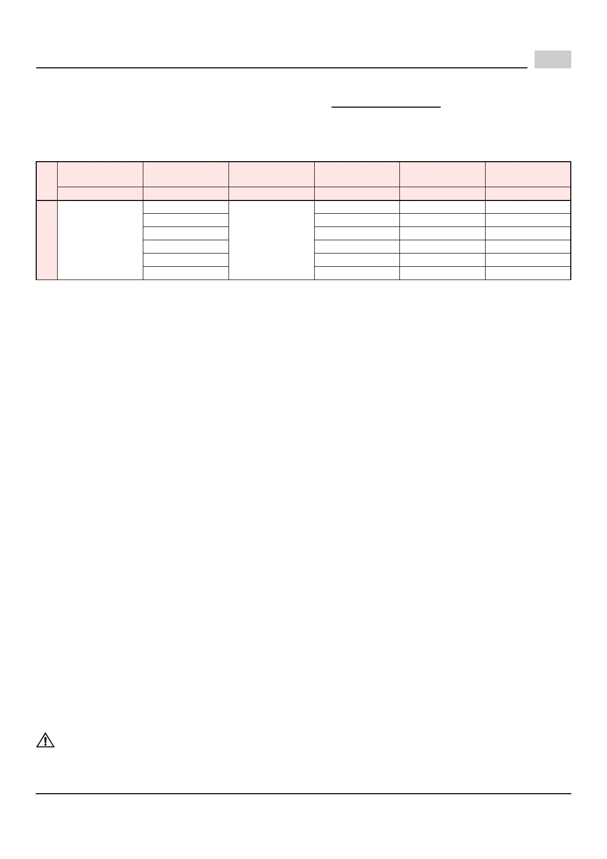
After burner output has been determined, use TABLE 1 below AS AN INITIAL GUIDE for burner settings.
All settings in this table were obtained under the following conditions.
O
0 (zero) draft in the combustion zone;
O
Standard lab test boiler;
O
Inlet gas pressure range as in table 1;
O
Steady state (HOT) operating conditions.
Burner input decreases with increasing the combustion chamber pressure.
Once installed, a higher or lower burner input can be achieved by raising or lowering the manifold pressure from - 0.5”
wc. to +1.5” wc. Pressure changes can only be made when the burner is running. The typical working manifold pressure
is 3.5” wc. (both for natuaral gas and propane).
STEP BY STEP PROCEDURE
1) Set air gate. See AIR GATE ADJUSTMENT on page 11.
2) Set gas orifice and combustion head.
See ORIFICE INSTALLATION AND COMBUSTION HEAD SETTING on page 12.
3) Set the manifold pressure using the following method.
a) In order to determine existing manifold pressure, start the burner.
At the end of the prepurge cycle (approx. 30s), the gas valve is energized.
During the 5 sec. trial for ignition, note the observed manifold pressure. If the burner lights and continues to
run, go to step (d).
b) Compare the observed manifold pressure from step (a) to the required value from TABLE 1.
c) Repeat step (a), making adjustments to the gas valve, until flame is established.
d) Once flame has been established, set your manifold pressure to the desired value from TABLE 1.
4) Check combustion gases using proper combustion analysis equipment to ensure safe levels of CO
2
and CO
during appliance heat up.
The gas valve should be used to make any necessary adjustments to ensure safe combustion.
At this point do not adjust the air or head settings unless absolutely necessary.
5) Allow burner to run until normal operating temperatures and conditions have been achieved.
6) a) Clock the gas meter to determine actual burner output.
b) Set the manifold pressure, by adjusting the gas valve, to achieve desired output.
c) Check combustion gases once again to ensure safe operation.
Make sure the burner cover is in place and air gate locking screws are secure for all combustion analysis.
Adjust air gate if necessary (refer to page 11). A qualified technician must do this test.
The maximum recommended CO
2
level for natural gas is 10%; the maximum recommended level for pro-
pane gas is 12%. The recommended flue gas temperature is from 350°F to 550°F.
7) After completing the adjustments, remove the manometer and tighten the screw inside the manifold test point.
Replace the regulator cap on the gas valve.
8) Complete the adjustment data tag, described on page 15.
Explain the burners essential functions (starting and stopping) to the owner.
Do not forget to give the dealer or service company's name and address.
Please see page 15 for information on burner maintenance procedures.
NOTE: Do not assume the heating system is operating at optimum performance.
THERE IS NO SUBSTITUTE FOR PROPER COMBUSTION TESTING!
OPERATING FAULTS
Gas inlet
pressure range
Orifice
Manifold
gas pressure
Burner
output
Head
setting
Air gate
setting
“wc Marking “wc Btu/hr Nocth Notch
NATURAL GAS
5.0 - 7.0
B1
3.5
75,000 0 1.5
B2 95,052 0 1.85
B3 114,589 1 1.9
B4 139,010 2 2.0
B5 159,673 3 2.3
B6 200,000 4 3.75
 Loading...