3254
9
GB
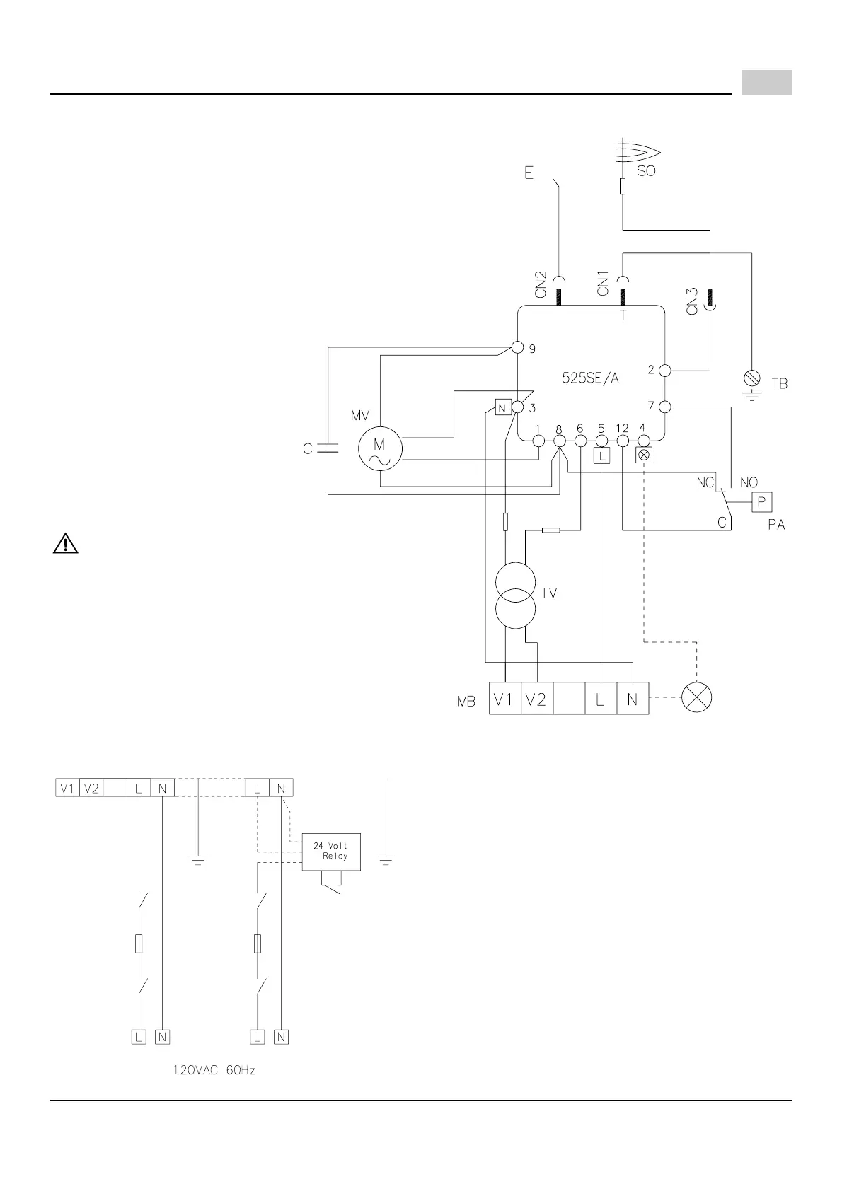
FACTORY WIRING DIAGRAM
NOTE:
The SAFETY SWITCH on the 525SE CONTROL BOX is
equipped with a contact allowing remote sensing of burner
lockout.
The electrical connection is located on the CONTROL BOX ter-
minal 4 as indicated. Should burner lockout occur, the 525SE
CONTROL BOX will supply a power source of 120 Vac to the
connection terminal.
The maximum allowable current draw on this terminal is 1A.
Blue
White
Black
D4703
LEGEND
C - Capacitor
CN... - Connectors
E - Ignition electrode
MB - Terminal board
MV -Motor
PA - Air pressure switch
SO - Ionization probe
TB - Burner earth
TV - Transformer 24V
Brown
Control box
Remote
lock-out
signal
Fuse Fuse
Service
D4704
switch
Service
switch
120V controlled 24V controlled
Operating
control
TB
TB
Operating
control
FIELD WIRING DIAGRAM
IMPORTANT:
Terminal 4 is to be used only for the connection of a
remote sensing device.
If a neutral or ground lead is attached to terminal 4,
the control box will be damaged should lockout occur.
 Loading...