3254
3
GB
GENERAL INFORMATION
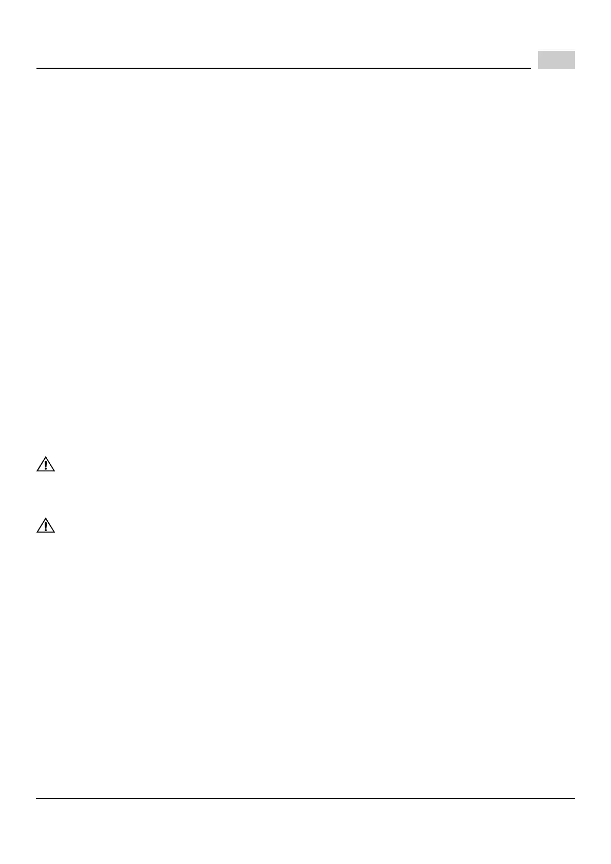
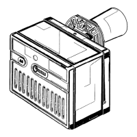
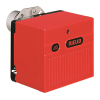
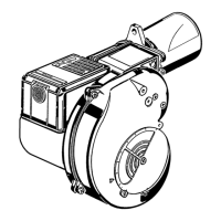
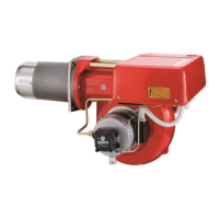
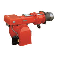
Your Riello gas burner comes to you completely assembled and factory wired, ready for installation.
Models equipped with the short combustion head have a fixed flange, which bolts directly to the front of the appli-
ance. When equipped with the long combustion head, the burner comes with a universal flange, which when bolt-
ed to the appliance, allows the burner to be adjusted for exact positioning in the combustion zone.
STEP-BY-STEP PROCEDURE
1) Remove the burner from the carton, taking care not to lose any of the supplied accessories.
Check for signs of physical damage.
2) Bolt the combustion head and burner to the appliance. Be sure to install the supplied mounting gasket.
Ensure that the burner is level (we suggest using a spirit level) and that the combustion head is centred in the
appliance port. Refer to page 7 for positioning of combustion head relative to the chamber.
3) Check that all gas train connections are tight and make your connections to the incoming gas supply.
a) A sediment trap must be provided. See page 8.
b) If not already installed, a manual shutoff valve must be supplied. This valve must be upstream of the burner
gas train supply connection.
c) A
1
/
8
" NPT plugged tapping must be installed immediately upstream of the burner gas train supply connec-
tion and must be accessible for a test gauge.
d) If required by local codes, provide gas vent lines at the gas regulators and valve (Riello gas trains are
equipped with vent limiting orifices).
e) Perform required gas pressure test on incoming gas supply lines.
NOTE: Details of sediment trap, manual gas valve, and pressure test point, and line pressure test point can be
found on page 8.
4) To make electrical connections, refer to field wiring diagram on page 9. A manual disconnect switch must be in-
stalled in the incoming lines. Wiring to the low voltage-switching relay, if used, (Honeywell R8038A) must be
rigid conduit or flexible approved cable.
CAUTION:
Label all wires prior to disconnection when servicing controls.
Wiring errors can cause improper and dangerous operation.
Verify proper operation after servicing. (Step 5 e below.)
CAUTION:
The phase (HOT) wire must be connected to the black lead of the 24v relay if used; neutral to the
white lead. Do not reverse the polarity.
The burner will not operate with the Phase/Neutral reversed, and the control box may be damaged.
5) Check the burner functions as follows:
a) Make a final check on both the gas and electrical connections.
b) Loosen the screw in the manifold gas test point and install an appropriate manometer.
c) Set the thermostat at its highest setting.
d) Switch on power.
e) With the manual gas valve turned off, press the burner reset button (9, page 4), and allow the burner to run
through a complete cycle to ensure that the sequence of operations is correct. A full starting cycle should
take approximately 40 seconds from a no power condition until burner lockout; refer to the start-up cycle
chart found on page 14.
f) Once burner is operational (up and running) a final gas leak check must be completed on the gas train.
6) If the burner is installed on a central warm air furnace, affix the mandatory warning labels to the furnace fan
cover door (inside and outside).